Collaborative robots (cobots) support industrial automation by enabling direct human-machine interaction. However, this operational flexibility introduces complex protective challenges that conventional safeguarding methods cannot adequately address. While the ISO/TS 15066 specification establishes the regulatory framework for safe human-robot collaboration, effective implementation requires machine vision systems capable of real-time spatial awareness.
Depth cameras provide the volumetric data necessary to implement speed and separation monitoring (SSM) and other collaborative operation modes. The evolution of 3D vision in robotics has accelerated the adoption of these vision-based systems as the cobot market grows across sectors.
Cobot Safety Standards: ISO 10218 and ISO/TS 15066
Understanding regulatory requirements is essential for implementing compliant systems. Standards for collaborative operations establish general industrial requirements and specific guidance for human-robot interaction scenarios.
ISO 10218 and ISO/TS 15066
ISO 10218 establishes the baseline requirements for all industrial robots and defines fundamental safeguarding principles. ISO/TS 15066 extends this framework by defining four collaborative operation modes:
- Safety-rated monitored stop: The cobot ceases all motion when a human enters the collaborative workspace and resumes operation only after the workspace is cleared.
- Hand guiding: An operator directs robot movement through a handheld device for direct control over trajectory and velocity.
- Power and force limiting: The machine’s design or control system limits forces to levels below injury thresholds, as defined by the specification’s permissible force and speed limits.
- Speed and separation monitoring: The system dynamically adjusts velocity based on the measured distance between the robot and human operators for continuous spatial awareness.
A Focus on SSM
SSM represents the most technically demanding collaborative mode and the primary application for cobot depth cameras in protective systems. It requires real-time tracking of machines and humans within the collaborative workspace.
The controller continuously calculates minimum separation distances. When an operator approaches, the system progressively reduces robot velocity, triggering a safety-rated stop if the separation distance falls below the calculated minimum protective distance.
Depth Camera Specifications for Collaborative Applications
Selecting a suitable 3D camera for critical applications requires careful evaluation of technical specifications that impact system reliability and regulatory compliance. A cobot safety camera must meet stringent performance criteria to ensure reliable human detection and tracking.
Range, Field of View (FOV), and Workspace Coverage
The camera detection range must cover all relevant safety zones throughout the collaborative workspace. Required sensing distance depends on robot reach, maximum speed, and total system response time.
While increasing the field of view can expand coverage, excessively wide-angle optics often introduce distortion, reduce spatial resolution, and degrade depth performance near image boundaries. For large or irregular workspaces, a multi-camera architecture is often the preferred solution.
Multiple synchronized depth cameras can be positioned to provide overlapping coverage and stitched spatial awareness across a larger operating area. This approach reduces blind spots, minimizes occlusion, and delivers more reliable workspace monitoring than a single ultra-wide camera.
Accuracy and Temporal Stability Requirements
For static conditions, measurement accuracy determines whether the controller receives position data of sufficient fidelity for reliable perception, obstacle localization, and motion planning. Inaccurate depth measurements can degrade environmental understanding or compromise protective separation margins.
For dynamic conditions, temporal stability is equally critical. As operators and robots move, the depth camera must provide consistent frame-to-frame measurements with minimal jitter, latency, or drift.
Unstable temporal performance can cause fluctuating zone boundaries, unnecessary slowdowns, or delayed protective responses.
Frame Rate and Latency
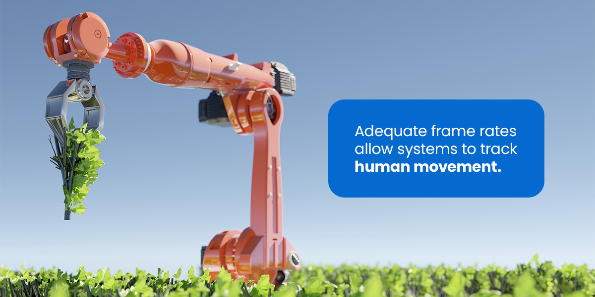
Frame rate defines the temporal resolution of dynamic scene monitoring, including operators and moving objects within a collaborative workspace. Adequate frame rates enable reliable motion tracking and timely updates to protective zones. Specific requirements depend on robot speed, human movement, and overall application risk assessment.
Camera latency contributes to total system response time. Minimizing latency throughout the perception pipeline improves reaction speed and reduces the stopping distance required to maintain safe collaborative operation.
Environmental and Interference Robustness
A depth camera must maintain stable perception performance under variable ambient lighting, including direct sunlight, strong shadows, and reflections from metallic or glossy surfaces. Environmental interference that degrades depth measurements can lead to unstable tracking, false protective triggers, or reduced operational efficiency.
Robust operation also depends on temperature variation, power supply stability, cable integrity, and interface reliability. In demanding manufacturing environments, appropriate ingress protection ratings are essential to ensure continued operation in the presence of dust, airborne particulates, moisture, and routine washdown conditions.
Safety Zone Configuration
Depth cameras support dynamic safety zones that adapt in real time based on the robot’s state and human proximity, and static safety zones that are fixed at commissioning and remain constant during operation.
Dynamic Safety Zones
Dynamic safety zones convert real-time perception data into adaptive protective boundaries that continuously adjust based on robot position, motion state, and workspace activity.
Zone dimensions are determined by maximum human approach speed, robot velocity, total system response time, stopping performance, and appropriate uncertainty margins in sensing and control. As a robot’s speed increases or its working envelope changes, protective boundaries update in real time.
A common multi-zone strategy includes a warning zone, a slowdown zone, and a stop zone. Entry into the warning zone may trigger visual or audible alerts. Penetration of the slowdown zone commands reduced robot speed, while entry into the stop zone initiates a safety-rated stop. This graduated response model maintains efficient operation while preserving required separation distances.
Static Safety Zones
Static safety zones define fixed, restricted areas within the collaborative workspace. Restrictions are established during commissioning and validated through a functional safety assessment. Common applications include safe access positions for maintenance or loading, and working envelope limits that apply regardless of robot speed or task.
Static zone monitoring places the highest demands on calibration stability. Drift in camera calibration, thermal expansion of mounting hardware, or subtle shifts in orientation can cause a zone boundary to migrate in the depth image. Periodic verification and recalibration are therefore essential to maintaining static zone integrity over the system’s operational life.
System Architecture and Integration
The depth camera operates as a perception layer within a broader functional safety architecture. It provides real-time spatial data to a safety-rated controller or programmable logic controller (PLC), which evaluates separation conditions and executes protective actions such as warning, speed reduction, or emergency stop. Reliable communication between the sensing and control layers relies on industrial interfaces and protocols tailored to the application.
Any critical fault condition, including power loss, communication interruption, invalid sensor output, or internal diagnostics failure, should force the system into a predefined safe state, typically a safety-rated stop or motion limit.
Safe robot cameras with mature SDKs, cross-platform software support, and well-documented interfaces reduce engineering effort across PLCs, robot controllers, and higher-level automation software. Selection criteria should also account for sensing performance, long-term integration cost, maintainability, and scalability within the target control architecture.
Implementation Challenges and Validation Considerations
Deploying vision-based safety systems introduces challenges beyond nominal hardware specifications. For example, false-positive detections can occur when nonhuman objects or moving equipment are misclassified as operators, leading to unnecessary slowdowns or production interruptions.
Reflective or transparent surfaces will degrade depth measurements, while dark, low-texture, or loosely draped materials can reduce detection reliability. These scenarios should be identified during risk assessment in accordance with ISO 12100 and verified through application-specific validation testing.
Long-term performance further depends on regular maintenance, periodic recalibration, and system health monitoring to ensure the safety function remains effective throughout deployment.
Vision-Based Cobot Safety Systems vs. Traditional Safeguarding
Traditional safeguarding devices, such as light curtains and safety laser scanners, remain effective for fixed hazards, but they are less suited to collaborative workspaces where humans and robots share space.
Traditional solutions provide limited spatial awareness:
- Light curtains: Light curtains create a protective plane that stops motion when interrupted, providing binary intrusion detection without distance or position awareness.
- Safety laser scanners: These scanners monitor configurable two-dimensional zones within a single plane, not the full workspace volume.
Vision-based cobot safety systems feature more adaptive protection:
- Volumetric perception: Depth cameras monitor operators, robot motion, and surrounding objects across the full workspace volume.
- Graduated responses: Real-time separation data enables warning alerts, speed reduction, and safety-rated stops based on actual risk.
- Software-defined zones: Protection zones can be reconfigured via software, enabling faster layout changes and easier scaling.
Deployment Support and Integration Services
Building an effective cobot vision safety system requires careful consideration of sensing performance, workspace coverage, latency, environmental robustness, system architecture, functional safety behavior, and long-term reliability in real deployment conditions.
Because these factors are tightly coupled, an effective vision-based system also requires engineering support across evaluation, integration, validation, and deployment. Orbbec helps customers navigate this process with technical expertise, flexible product options, and global support resources for faster development and more reliable implementation of cobot safety solutions.
FAQ: Depth Cameras for Cobot Safety Systems
What standards govern cobot safety in collaborative workspaces?
ISO 10218 sets the baseline requirements for industrial robots and fundamental safeguarding principles. ISO/TS 15066 extends that framework for human-robot collaboration specifically, defining four collaborative operation modes: safety-rated monitored stop, hand guiding, power and force limiting, and speed and separation monitoring.
What is speed and separation monitoring, and why does it require a depth camera?
SSM continuously calculates the distance between a robot and nearby operators and adjusts robot velocity in real time. This requires volumetric spatial data that 2D sensors like light curtains or laser scanners can’t provide. Depth cameras supply the 3D perception layer that makes SSM possible.
What depth camera specifications matter most for cobot safety applications?
Detection range has to cover all safety zones given the robot’s reach and maximum speed. Frame rate and latency affect total system response time. Measurement accuracy and temporal stability determine whether the controller receives reliable position data frame to frame. Environmental robustness matters too: performance needs to hold under variable lighting, reflective surfaces, dust, and temperature swings.
When is a multi-camera setup the right call?
Wide-angle optics introduce distortion and lose depth accuracy at image boundaries, so a single camera isn’t always the answer for large or irregular workspaces. Multiple synchronized depth cameras positioned for overlapping coverage typically produce more reliable monitoring with fewer blind spots than pushing the limits of one wide-angle unit.
What’s the difference between dynamic and static safety zones?
Dynamic zones adjust continuously during operation based on robot speed, position, and human proximity. Static zones are fixed at commissioning and don’t change regardless of robot state. Static zones are more demanding from a calibration standpoint: drift in camera alignment can cause zone boundaries to shift over time, so periodic verification is part of maintaining them.
How do vision-based safety systems differ from light curtains or laser scanners?
Light curtains detect binary intrusion across a single plane. Safety laser scanners monitor configurable 2D zones. Depth camera systems monitor the full workspace volume, support graduated responses (warning, slowdown, stop) based on actual measured separation distance, and allow protection zones to be reconfigured in software rather than through physical hardware changes.
What are the most common implementation challenges?
False-positive detections from non-human objects, degraded depth measurements off reflective or transparent surfaces, and reduced detection reliability on dark or low-texture materials are the most frequent issues. These scenarios should be identified during risk assessment per ISO 12100 and verified through application-specific testing before deployment.