
A GMSL2 link can lock while the robot still has no usable image. A video node can appear while the SDK still cannot start depth. Two cameras can stream independently and then fail when enabled together. These outcomes are not contradictory: each milestone proves only one layer of a much larger system.
For a production robot, the camera is one component in a versioned stack: camera firmware → serializer and cable → deserializer and carrier → CSI routing and device tree → kernel driver → camera SDK → ROS 2 or the application. Changing any link in that chain can change bandwidth, startup, synchronization, recovery, or the available stream combination.
This guide assumes the interface decision has already been made. If you are still deciding between USB, Ethernet, and GMSL2, start with the interface-selection article in this series. Here, the question is different: how do you turn a GMSL2 camera connection into a reproducible robot-vision subsystem?
The central principle: “GMSL2 compatible” is not a complete integration specification. The deployable unit is the exact camera, firmware, serializer, cable and PoC network, deserializer board, host and carrier, operating-system release, kernel driver, device tree, SDK, and application configuration that were tested together.
1. Start with the data contract, not the cable
A conventional GMSL camera example often begins with one RAW image stream from one sensor. A stereo or RGB-D camera can be more demanding. Depending on the product and mode, the host may need depth, left and right infrared, RGB, metadata, and IMU data. Some data may be produced in the camera; other data may be transported as sensor streams and processed elsewhere. The first integration document should therefore describe the output contract before it names the SerDes parts.
- List every stream that must run at the same time, including resolution, frame rate, pixel format, bit depth, and metadata.
- Separate mandatory production streams from streams used only for commissioning, diagnostics, or calibration.
- Record where depth is generated and which raw inputs, if any, must reach the host.
- Define the acceptable latency, jitter, frame-drop, and recovery behavior at the application boundary – not only at the cable.
A first-pass payload estimate is straightforward:
then add transport, packetization, metadata, and implementation margin
Run that budget twice. The first pass checks the camera-to-deserializer links. The second checks the deserializer outputs, CSI lane rates, virtual-channel allocation, SoC camera inputs, video-input resources, memory traffic, and downstream processing. A healthy GMSL2 link does not guarantee that the host ingress or memory path can accept the selected combination.
Orbbec’s public GMSL documentation explicitly treats RGB-D cameras differently from single-stream RGB cameras and documents version- and topology-dependent stream restrictions. The practical lesson is to validate the exact concurrent profiles, not just the number of connected cameras. See the current Orbbec GMSL usage notes for the supported combinations in the driver release you intend to ship.
2. Freeze the complete topology before ordering hardware
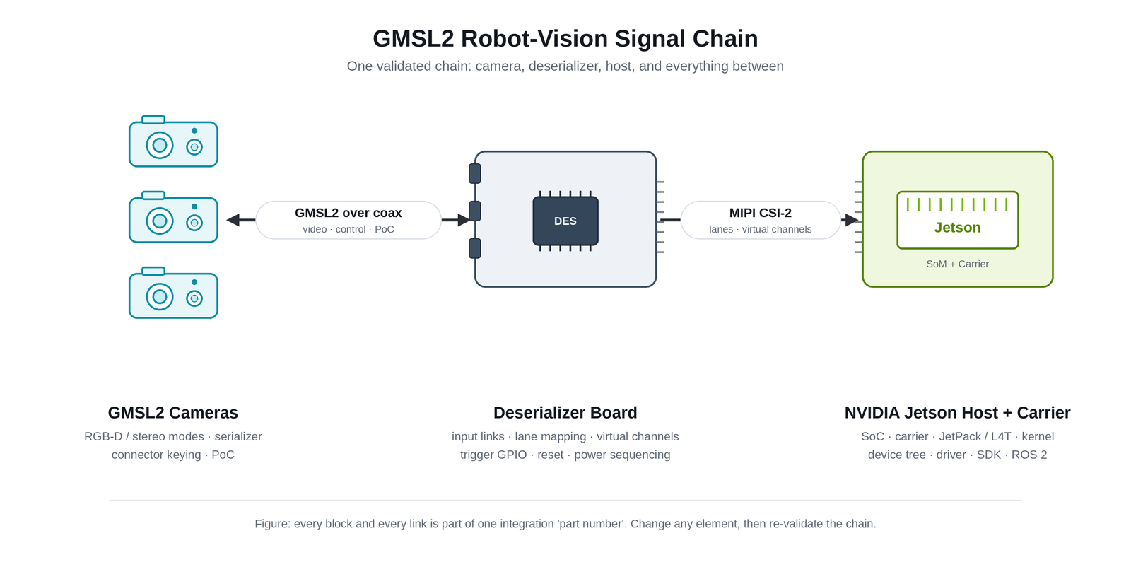
A useful architecture drawing should show more than “camera → Jetson.” At minimum, identify:
- Camera model, firmware, sensor modes, serializer, connector keying, and any service or USB path.
- Cable part number, impedance, length, bend requirement, shielding and retention, plus the Power-over-Coax network.
- Deserializer part, board revision, input link, CSI output, lane mapping, virtual channels, trigger GPIO, reset, and power control.
- Host SoC, carrier board, JetPack/L4T release, kernel, device-tree overlay, driver package, camera SDK, ROS distribution, and application version.
- Support owner for each layer: Orbbec reference package, integration partner image, or custom carrier/driver work.
This is the integration “part number.” A shared serializer or deserializer family does not make two systems interchangeable. The I²C wiring, CSI ports, lane count, virtual-channel mapping, reset and synchronization routes, power sequence, and software package still need to match the board.
The Orbbec supported-host matrix is the correct place to check current camera, host, JetPack, driver, and support-owner combinations. Do not copy its entire version table into a design document and assume it will remain current. Instead, record the matrix revision or access date and pin the exact validated combination in the project BOM.
3. Treat SerDes as both a data plane and a control plane
The forward path carries high-rate video. The reverse path can carry control traffic, and the link can also transport GPIO-related functions depending on the implementation. That makes bring-up a coordinated sequence rather than a passive cable connection.
At initialization, the host may need to configure the deserializer, establish the link, assign or translate I²C addresses, configure the serializer and camera, map stream data types to virtual channels, program CSI outputs, and then start streaming. Multi-camera designs add duplicate-address management, shared power and reset behavior, link ordering, and resource allocation.
NVIDIA’s current GMSL architecture documentation makes those roles explicit in its SIPL/UDDF framework: the camera module, serializer, deserializer, sensor and power controls each have a lifecycle. Even when a current integration uses a different Linux camera path, the ownership model is still useful: every reset, address, link, error and stream transition needs one responsible component.
Do not over-read “link lock.” It demonstrates that a specific SerDes boundary has been established. It does not prove that the sensor is configured, CSI packets are valid, virtual channels reach the correct endpoint, video nodes expose the expected formats, depth starts in the SDK, timestamps are coherent, or the application can recover from a fault.
4. Design Power over Coax and the harness as one subsystem
Power over Coax (PoC) can consolidate power, video and bidirectional control on one cable, but it couples the power and signal-integrity designs. The power injector and extractor filters must pass DC without compromising the high-frequency channel. Startup current, steady-state current, voltage drop, transient response, short-circuit behavior and recovery all have to work at the camera – not only at the bench supply.
- Budget worst-case input voltage at the camera across temperature, maximum cable length, connector losses, and startup current.
- Confirm the PoC filter, protection and independent power/fault-monitoring scheme for the selected SerDes and board – not for a generic GMSL2 diagram.
- Use the specified impedance and insertion/return-loss channel; include adapters, bulkheads and board connectors in the channel budget.
- Check minimum bend radius, torsion, routing near motors and switching power electronics, connector retention, assembly access, and service replacement.
- Define whether connection or disconnection under power is permitted. If the supplier does not document hot-plug support, design and operate the system as power-off connection.
ADI’s PoC line-fault design note explains why PoC changes fault detection and requires a suitable filter and protection strategy. For a concrete Orbbec example, the Gemini 335Lg cable guidance treats impedance, length, loss, flexibility and bend radius as engineering variables. Use the cable guide for the exact camera model rather than turning one model’s limit into a family-wide claim.
5. Choose one host software path – and version-lock it
A recurring source of wasted time is combining instructions from different Jetson generations or camera frameworks. Current public Orbbec packages for supported Jetson configurations use a Linux V4L2 and device-tree integration path. The Orbbec MIPI Camera Platform Driver repository provides release-specific packages, patches, documentation and tools for documented boards and JetPack releases. NVIDIA also documents a SIPL/UDDF-based GMSL path for specific newer platform and software combinations. These are not interchangeable snippets.
Table 1. V4L2/device-tree vs SIPL/UDDF path comparison
| Decision | V4L2 / device-tree path | SIPL / UDDF path |
|---|---|---|
| Use when | The selected Orbbec host package and board documentation specify this path. | The target NVIDIA platform, JetPack release and camera integration explicitly specify SIPL/UDDF. |
| Configure | Kernel modules, board-specific DT/DTBO, I²C, CSI ports/lanes, virtual channels and endpoints. | UDDF devices and platform blocks, drivers, link modes, CSI/PHY mapping and lifecycle. |
| Do not assume | A module built for one kernel, JetPack or carrier will load and route correctly on another. | A SIPL example proves support for a current Orbbec camera/board unless that combination is documented. |
Pin the complete software baseline: camera firmware, driver release, JetPack/L4T and kernel, board image or overlay, Orbbec SDK, ROS 2 wrapper and distribution, build toolchain, application, and configuration files. “Use the latest” is not a production configuration. Upgrade one layer at a time and retain a rollback image.
On supported models, USB can remain valuable as a development baseline, service connection or firmware-recovery path. Passing a USB test proves that the camera and a portion of the application stack work; it does not validate the GMSL cable, PoC, deserializer, CSI routing, synchronization or kernel integration.
6. Bring up one link as a ladder of evidence
Begin with one camera, one deserializer input and one CSI output. Expand only after the first stream is repeatable. This creates a clean fault boundary and matches the approach in Orbbec’s G300 GMSL Camera Driver Quick Start Guide.
- Record the exact hardware and software manifest. Photograph connector positions and note the deserializer link used.
- Verify the power-off cable installation, PoC supply and expected current behavior before boot.
- Confirm that the board-specific kernel modules load and the deserializer and camera drivers probe.
- Check I²C communication and SerDes lock. Treat each as a separate result.
- Validate the selected sensor mode, CSI port and lane routing, data types, virtual-channel IDs and remote endpoints.
- Confirm that the expected video nodes exist and enumerate the advertised formats.
- Stream one raw node with V4L2 before opening a higher-level viewer or SDK.
- Start the required RGB, depth, IR and metadata combination in OrbbecViewer or the Orbbec SDK.
- Integrate ROS 2 or the application only after the lower layers are repeatable across cold boot and restart.
Typical first-line checks on a current Linux package include:
uname -r
 lsmod | grep -E "g300|obc_max9296|obc_max96712"
 dmesg | grep -i orbbec
 dmesg | grep -Ei "g300|max9296|max96712"
 v4l2-ctl --list-devices
 ls /dev/video*
 v4l2-ctl -d /dev/video0 --list-formats-ext
 v4l2-ctl -d /dev/video0 --stream-mmap
Module names and node numbering are release- and topology-dependent. Copy the commands from the Quick Start that matches the installed driver package, and save complete boot logs before changing multiple variables.
7. Synchronization is four different contracts
“The cameras are synchronized” is too vague for a robot. At least four timing relationships should be specified and measured independently:
Table 2. Four timing contracts for camera synchronization
| Timing contract | What it means | How to verify |
|---|---|---|
| Internal stereo timing | The image pair used to compute depth represents the intended exposure relationship. | Use the camera’s documented mode and inspect depth behavior on motion and discontinuities. |
| Camera-to-camera exposure | Multiple cameras expose according to a shared trigger or defined phase relationship. | Observe the trigger at endpoints and measure image response to a time-resolved target. |
| Timestamp alignment | Frames carry timestamps in a defined clock domain with known offset and drift. | Log timestamps against host/robot time and test startup, long runs, restarts and dropped frames. |
| Camera-to-robot / IMU time | Perception data can be associated with motion, control and other sensors. | Measure end-to-end offset and jitter at the application boundary; do not infer it from transport latency. |
GMSL2 can provide a transport path for synchronization signals, but achieved synchronization accuracy is a property of the complete camera-SerDes-host implementation. Orbbec’s Gemini 335Lg hardware-synchronization guide documents a model- and configuration-specific host-trigger path through a compatible deserializer and GPIO mapping. Do not extrapolate one reference result to every camera, carrier, cable or software release.
ROS 2 message filters can associate messages by timestamps. They do not make sensor exposures simultaneous. Hardware trigger, camera configuration, timestamp generation, clock alignment and application-level association are different layers, and all must be validated for the robot’s motion speed and error budget.
8. Troubleshoot by asking what the latest milestone actually proves
A layer-based diagnosis prevents the common reaction of changing cable, device tree and SDK at the same time. Preserve the last known-good baseline and move upward only after each boundary is proven.
Table 3. Troubleshooting ladder for GMSL2 integration
| Observed state | What it proves | Inspect next |
|---|---|---|
| No driver probe or I²C response | The software has not established control of the expected devices. | Power/reset, board image, bus/address, overlay selection, module-kernel match and connector orientation. |
| I²C works; no SerDes lock | The control bus is reachable, but the high-speed link is not established. | Link mode/rate, serializer state, cable/channel, PoC voltage at camera, link port and deserializer configuration. |
| Link locked; no video node | The SerDes physical/data boundary is up. | Sensor mode, CSI output, lanes, data type, VC IDs, DT endpoints, NVCSI/VI errors and driver registration. |
| Video node exists; no raw frames | The Linux media device registered. | Advertised format, stream pairing, CSI errors, frame start/end, bandwidth, node selection and metadata mode. |
| Raw V4L2 works; SDK fails | Kernel capture works for at least one stream. | Firmware/SDK compatibility, expected node mapping, metadata layout, profiles, permissions and process ownership. |
| Each camera works alone; group fails | Single-link integration is valid. | PoC capacity, address aliases, VC collisions, CSI/VI resources, concurrent stream restrictions, memory and sync routing. |
| System is intermittent after motion or heat | The nominal bench path is insufficiently robust. | Connector retention, cable routing/loss, supply margin, thermal state, EMI, error counters, reset/recovery and soak logs. |
The recovery design deserves its own test plan. A development script that unloads and reloads modules can be useful during bring-up, but production software needs an explicit policy: detect a fault, identify the affected link, preserve diagnostics, reset the smallest safe boundary, re-establish configuration, restore streams, and tell the application whether timing and calibration state remain valid.
9. Scale from one camera only after allocating shared resources
Multi-camera systems fail at shared boundaries. Before adding the second link, assign and document:
- Deserializer inputs, serializer aliases and any duplicate sensor addresses.
- Virtual-channel IDs, data types, CSI outputs, lane counts, SoC camera inputs and video nodes.
- Concurrent stream profiles and the bandwidth budget at both the GMSL and host-ingress sides.
- PoC startup and steady-state current, fault isolation, reset groups and cable assembly order.
- Trigger distribution, camera roles, timestamp domains and behavior when one camera drops or restarts.
- Driver and board-image ownership, including who supplies updates after JetPack or carrier revisions.
Camera count is a system result, not a camera-only specification. Current Orbbec documentation describes validated four- and eight-camera configurations depending on the host and carrier, while the usable stream mix also depends on the deserializer topology, driver version and selected profiles. Always consult the live supported-host matrix instead of treating a headline number as a universal GMSL2 limit.
10. Move from a working link to a manufacturable product
The first frame is a development milestone. Production readiness means the subsystem behaves predictably over the robot’s operating envelope and can be built, updated, serviced and diagnosed at scale.
- Reliability: cold/warm boot, repeated restart, brownout, link interruption, thermal cycling, cable motion, vibration, long-duration streaming and controlled fault injection.
- Telemetry: link state and errors, driver and CSI errors, frame counters, timestamps, dropped frames, temperature, resets, firmware and software versions.
- Update and recovery: signed or controlled artifacts, compatibility checks, staged rollout, rollback image and a documented service path.
- Manufacturing: cable and connector work instructions, board and camera serialization, calibration handling, end-of-line tests, golden logs and traceable configuration.
- Change control: approved substitutes, carrier/JetPack/driver qualification, regression test ownership and field-support responsibility.
At this point, the engagement model matters. Contract Manufacturing (CM) is suited to programs with a substantially defined design that need NPI, supply-chain, quality, manufacturing, delivery, and after-sales support. For qualifying robotics and intelligent-vision products that still have gaps in vision-related hardware design, calibration, integration, validation, or production readiness, Joint Design Manufacturing (JDM) can extend that support earlier into productization. Orbbec’s CM/JDM scope is centered on hardware, vision-system integration, and manufacturability – not independent software development or general-purpose algorithm outsourcing.
11. Use integration gates, not one final demo
Table 4. Integration gates for GMSL2 robot vision
| Gate | Exit evidence |
|---|---|
| 1 – Configuration | Signed-off topology and version manifest; owners defined for camera, board, driver, SDK and application. |
| 2 – Electrical and link | Power margin, cable/channel compliance, repeatable I²C and link lock, protected fault behavior. |
| 3 – Video and software | Required raw nodes and concurrent profiles work across cold boot, restart and controlled updates. |
| 4 – Timing | Measured exposure, timestamp and robot/IMU alignment meet the task-level budget. |
| 5 – Reliability | Soak, thermal, motion, interruption and recovery tests meet explicit pass/fail criteria with useful telemetry. |
| 6 – Production | Work instructions, calibration/validation, end-of-line tests, version control, rollback and service process are ready. |
These gates answer an engineering question: does each layer work and can a failure be isolated? They are not a product-selection scorecard. The next article in this series will address how to compare candidate cameras and host combinations against the robot’s task, environment and POC acceptance criteria.
Frequently asked questions
What hardware is required to connect a GMSL2 camera to NVIDIA Jetson?
You need a camera with a compatible serializer, the specified cable and PoC design, a deserializer board that routes its outputs to the selected Jetson carrier/CSI inputs, and a software package for that exact host and JetPack release. A GMSL2 camera cannot be connected directly to an ordinary CSI connector without the matching deserializer and integration.
Does GMSL2 carry video, power, control and synchronization over one cable?
A GMSL2 implementation can carry high-rate video and a bidirectional control channel; PoC and GPIO transport can consolidate power and synchronization-related signals in a compatible design. The exact functions depend on the camera, serializer, deserializer, board wiring, filters and software configuration. “One cable” does not remove those engineering contracts.
Why can the GMSL2 link be locked while no video appears?
Link lock proves the SerDes connection, not the complete camera path. The sensor may still be unconfigured, CSI data types or virtual channels may be mapped incorrectly, the device-tree endpoints may not match the carrier, or the Linux video nodes and SDK may expect a different stream or metadata layout.
Does every GMSL2 camera require a custom Jetson driver?
Not necessarily. Orbbec publishes validated reference configurations and prebuilt packages for selected Jetson platforms, and turnkey partner systems may use partner-maintained images or drivers. A custom carrier, deserializer topology, CSI route, JetPack release or unsupported camera combination normally requires adaptation and qualification.
How are multiple GMSL2 cameras synchronized?
A host or timing source generates the trigger, the carrier and SerDes route it, each camera is configured for a defined role, and the application interprets timestamps in a known clock domain. The supported path and achieved accuracy are configuration-specific. Measure exposure timing and timestamp behavior end to end.
What is the difference between hardware synchronization and ROS timestamp matching?
Hardware synchronization controls or relates exposure timing. ROS message filters associate already-captured messages by timestamps. Software association can be useful, but it cannot retroactively make two exposures simultaneous or remove an unknown clock offset.
How many GMSL2 cameras can one Jetson host support?
There is no single GMSL2 answer. The result depends on the Jetson and carrier, deserializers, CSI and VI resources, virtual channels, power, driver release, camera firmware, and concurrent stream profiles. Use the current validated host matrix and test the exact production configuration.
Can a GMSL2 camera be hot-plugged?
Only if the complete camera, cable, PoC, deserializer, carrier, driver and application explicitly support and validate that behavior. Current bring-up instructions commonly require power-off connection. Do not assume connector robustness or link recovery implies safe electrical hot-plug operation.
Build a reproducible vision subsystem
GMSL2 solves a demanding transport problem, but the robot still needs a coherent subsystem. Start with the data contract, freeze the full topology, bring up one link as a ladder of evidence, measure timing at the application boundary, and scale only after the shared resources are allocated. Then turn the validated configuration into a controlled manufacturing and service baseline.
Moving a GMSL2 robot-vision design toward production? Contact Orbbec to review the camera architecture, vision-hardware integration gaps, calibration and validation plan, and NPI needs. CM/JDM engagements are evaluated and scoped project by project for robotics and intelligent-vision hardware.
Sources and further reading
- Analog Devices – Building High Performance Robotic Vision with GMSL – GMSL architecture, control path, PoC and multi-camera topology concepts.
- Analog Devices – GMSL line-fault detection with Power over Coax – PoC filtering, protection and fault-detection considerations.
- NVIDIA – GMSL Architecture Overview – Current SIPL/UDDF architecture and driver responsibilities.
- NVIDIA – GMSL Camera Development – Platform components and lifecycle for SIPL integrations.
- Orbbec – Supported GMSL hosts and system requirements – Live compatibility, camera count, driver version and support-owner matrix.
- Orbbec – MIPI Camera Platform Driver – Public packages, documentation, patches and tools for documented GMSL integrations.
- Orbbec – G300 GMSL Camera Driver Quick Start Guide – Board-specific installation, device-tree, diagnostic and raw-stream workflow.
- Orbbec – Instructions for Using GMSL Camera – Version- and topology-dependent stream restrictions.
- Orbbec – Gemini 335Lg Hardware Synchronization – Model-specific trigger and synchronization configuration.
- Orbbec – Gemini 335Lg Recommended Cable Specifications – Cable impedance, loss, length, flexibility and bend-radius guidance.
- Orbbec – OrbbecSDK v2 – SDK packages, tools and current release information.
- Orbbec – OrbbecSDK ROS 2 – Current ROS 2 wrapper and camera launch configurations.
- ROS 2 – Approximate Time Synchronizer – Application-level timestamp association; not exposure synchronization.
Ready to Integrate GMSL2 Vision?
Contact Orbbec to review your camera architecture, integration gaps, and production readiness. Our team supports CM/JDM engagements for robotics and intelligent-vision hardware.