Choosing a robot camera interface is not a contest between three peak data rates. It is a decision about topology, power, timing, compute placement, serviceability, and where the engineering team is willing to carry integration risk.
Executive Snapshot
A depth camera, such as one from the Gemini 330 series, connected to a development PC through a short USB cable is not the same system as four cameras distributed around a mobile base, streaming to a production compute module while motors, batteries, and high-current switching share the enclosure. The sensor may be unchanged, yet the interface becomes part of the robot’s power, mechanical, timing, thermal, and recovery architecture.
There is no interface winner outside a defined system. A useful first pass is:
- Choose USB when cable runs are short and controlled, camera count is limited, host-controller topology is known, and fast bring-up matters.
- Choose Ethernet when cameras are distributed, standard network cabling and PoE are valuable, and field serviceability matters more than minimum host-side complexity.
- Choose GMSL2 when several high-bandwidth cameras feed centralized compute, harness size and motion matter, and the team can own the deserializer, carrier, driver, power, and synchronization stack.
- Use a hybrid architecture when different sensors have different jobs. Procurement symmetry is not a system requirement.
The correct sequence is to define the perception workload and physical deployment first, calculate the data and timing budget second, and select the interface third. Reversing that order often produces an elegant cable diagram attached to the wrong robot.
A Camera Interface Is a System Architecture Decision
Begin with the robot rather than the connector. What perception task must succeed? How many cameras are required? Where are they mounted relative to compute? Do cables cross joints or moving assemblies? Can the robot stop safely after a lost frame? Who replaces a failed camera in the field, and what diagnostic tools will that person have? These questions determine whether the dominant constraint is bandwidth, harnessing, timing, host resources, recovery, or maintenance.
Four layers are routinely collapsed into one label: the physical connector, the transport technology, the camera protocol or API, and the complete camera-to-host implementation. They are not interchangeable. FAKRA is a connector family, not GMSL2. USB Type-C describes a connector, not a guaranteed data rate or power profile. Ethernet is a networking technology, not a promise that a camera implements GigE Vision. Treating these labels as synonyms is how architecture diagrams acquire confidence faster than accuracy.
The USB-IF cable and connector guidance is a useful reminder that cable capability, identification, power delivery, and signaling must be verified as a system. Likewise, the machine-vision standards described by A3 are specific protocol ecosystems: a USB camera is not automatically a USB3 Vision device, and an Ethernet camera is not automatically a GigE Vision device.
For each candidate interface, draw the entire path: camera electronics, cable and connector, power source, intermediate hub, switch or deserializer, host controller or CSI input, driver, middleware, and perception application. If a component is absent from the diagram but required to make frames arrive, it has not disappeared; it has merely escaped the budget.
First Ask What Actually Crosses the Link
A “camera stream” may mean raw Bayer data, two raw stereo imagers, rectified infrared, RGB, device-generated depth, IMU samples, calibration data, metadata, or several of these at once. A camera that computes depth internally presents a different host and transport problem from a raw stereo module that sends both imagers to the SoC for processing. Resolution alone therefore says little about the real interface load.
A useful first-order payload estimate is: width × height × bits per pixel × frame rate × number of streams × number of cameras. Add protocol overhead and engineering margin, then compare the result with measured sustainable payload—not the connector’s advertised line rate. Also check burst behavior: several streams that begin on the same frame boundary can stress buffers even when their average rate appears comfortable.
Latency also needs boundaries. Exposure time, sensor readout, on-camera image or depth processing, link transport, host buffering and driver behavior, middleware queues, and application processing all contribute to the control-loop delay. A low-latency transport cannot compensate for an uncontrolled queue elsewhere. Measure both distribution and worst credible excursions; an average can hide the frame that makes the robot brake late.
Synchronization is equally layered. Trigger generation, exposure alignment, serializer and deserializer behavior, timestamp domains, host delivery, and application-level frame association are separate mechanisms. “Synchronized cameras” is not a complete specification until the system states what event is aligned, where it is measured, and how much skew is acceptable.
When USB Is the Right Production Choice
USB has real production advantages: broad host support, low incremental hardware cost, fast development, mature diagnostics, and straightforward access through UVC or a vendor SDK. It is often the lowest-risk choice for a compact robot with one or two nearby cameras, especially when the enclosure controls the cable, connector retention, strain relief, power source, and host configuration.
The phrase “USB is only for prototypes” is wrong. The engineering question is whether the implementation is controlled. Multiple external ports may share one xHCI controller or PCIe path. A hub can add power and recovery behavior that was absent in the single-camera bench test. Passive-cable signal integrity, connector retention, voltage drop, peak current, hot-plug handling, operating-system recovery, and thermal conditions can all become system limits.
Do not infer capability from a Type-C receptacle. Confirm the negotiated mode, cable rating, controller topology, power budget, and actual camera stream set. The USB-IF’s public guidance explains why connector appearance alone is insufficient. Also keep UVC, vendor SDK transport, and USB3 Vision separate. A3’s USB3 Vision overview describes an industrial machine-vision standard built on USB 3.x; those features apply only when the camera and host software implement that standard.
A credible USB POC should run the final camera count, resolution, frame rate, and stream combination while logging frame numbers, timestamp continuity, controller utilization, CPU load, disconnects, and recovery time. Add power transients, cable bending, vibration at the real mounting points, temperature, and repeated application or host restarts. If the test uses a different hub, cable, controller, or power source than production, it is a demonstration—not design-in evidence.
When Ethernet Is the Better Architecture
Ethernet becomes attractive when cameras are physically distributed, cable runs are longer, standard network infrastructure is already present, or field replacement and remote diagnostics matter. PoE can consolidate data and power, switches can support flexible topologies, and familiar network tools can make link state, packet behavior, addressing, and device reachability visible to service teams.
But “Ethernet camera” describes the transport family, not the complete camera protocol. A device may implement GigE Vision, a vendor SDK over Ethernet, a custom streaming protocol, or another design. A3’s GigE Vision overview defines a specific machine-vision standard; it should not be attributed to a product unless the product documentation says it is supported. Ethernet also does not imply that video is compressed. Compression, packetization, and on-camera processing are implementation choices.
The system risks shift rather than disappear: shared bandwidth, packet loss, jitter, switch buffering, NIC and driver settings, interrupt load, IP addressing and discovery, PoE budget, network security, and recovery after link interruption. If precise timing is required, verify the actual PTP or hardware-trigger implementation end to end. A network cable does not manufacture deterministic exposure timing by itself.
The Ethernet POC should measure sustainable payload, packet and frame loss, latency distribution, timestamp behavior, CPU and NIC load, switch utilization, PoE margin, and recovery after cable, switch, camera, and host faults. Test field replacement as an operational workflow: can a technician identify the device, restore its configuration, and confirm that the correct calibration and application mapping returned?
When GMSL2 Earns Its Integration Cost
A typical GMSL2 vision path is camera sensor or camera processing → serializer → coaxial or shielded twisted-pair cable → deserializer or aggregator → CSI-2 and the host SoC. Bidirectional control, GPIO or synchronization signals, diagnostics, and power-over-coax options are part of the design. Analog Devices’ robotic-vision overview describes GMSL as a high-speed SerDes link that can carry video, bidirectional control, and power over a single cable; the exact rate, reach, topology, and power behavior still depend on the selected components and implementation.
This architecture is compelling when several high-bandwidth cameras must converge on centralized compute, the camera locations move or leave little space for bulky harnessing, and link timing must be tightly controlled. It can reduce camera-side electronics and support deterministic transport behavior. It can also simplify aggregation compared with treating every camera as a separate general-purpose peripheral or network node.
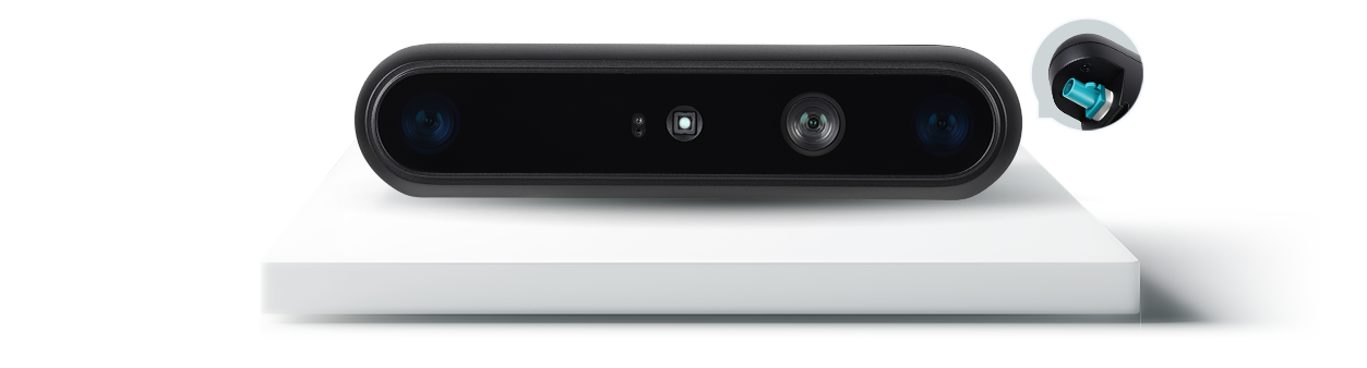
The integration cost is real. The design must match camera module, serializer, cable, connector, power architecture, deserializer, virtual channels, CSI lanes, carrier board, SoC, driver, and software configuration. NVIDIA’s GMSL architecture overview and SIPL documentation show why the host path includes more than plugging a FAKRA cable into a board. Camera modules, deserializers, drivers, platform configuration, and frame synchronization must agree.
GMSL2 is a proprietary SerDes technology, not an open, cross-vendor camera interoperability standard. It does not automatically make the complete robot immune to EMI, guarantee multi-camera exposure alignment, eliminate dropped frames, or make every host compatible. Its transport latency may be low and predictable, but end-to-end latency still includes sensor, camera processing, host, middleware, and application stages.
A GMSL2 POC should monitor link lock, error counters, frame and timestamp continuity, synchronization skew, power margin, cable and connector behavior, driver recovery, and full-camera-count soak performance. Qualify the exact deserializer, carrier, cable assembly, power configuration, Jetson or SoC software release, and driver owner. “Compatible with GMSL2” is a starting condition, not a completed integration plan.
Comparison Matrix: Compare Architectures, Not Marketing Labels
The matrix below summarizes common architecture patterns. Every cell is conditional; the final decision must use the actual camera output, topology, host, environment, and failure requirements.
Table 1. Architecture-first comparison of USB, Ethernet, and GMSL2
| Decision dimension | USB | Ethernet | GMSL2 |
|---|---|---|---|
| Typical topology | Direct camera-to-host bus | Camera as a network node, often through a switch | Point-to-point SerDes links aggregated into CSI/SoC |
| Best fit | Short, controlled runs; limited camera count; fast bring-up | Distributed devices; longer standard cabling; field serviceability | Centralized multi-camera compute; motion-sensitive harnesses; controlled timing |
| Power path | Bus power or separate DC; verify peak current and voltage drop | PoE or separate DC; verify switch and total power budget | Power over coax or separate rail; implementation-specific |
| Synchronization | Device trigger and timestamps when supported | PTP and/or external trigger when implemented | Frame-sync/trigger path across camera, SerDes, and host stack |
| Host requirements | USB controller, bandwidth, power, driver/SDK | NIC, switch, network configuration, driver/SDK | Deserializer, carrier, CSI resources, platform driver/configuration |
| Scaling limit | Shared controller paths, hubs, host bandwidth, power | Link, switch fabric, NIC, packet processing, PoE budget | Deserializer inputs, virtual channels, CSI lanes, SoC and driver support |
| Primary risks | Cable integrity, retention, shared controller, power and recovery | Loss/jitter, buffering, configuration, timing, security and recovery | Platform matching, harness/power qualification, driver integration and lock-in |
| Diagnostics | USB topology, controller logs, SDK counters, reconnect tests | Packet/NIC/switch/PTP tools plus camera logs | Link lock/error counters, SerDes and platform-driver logs |
| System cost pattern | Low initial NRE; cost can rise when hubs, extenders, or custom retention are added | Network hardware and configuration; often strong serviceability | Higher BOM/NRE and validation; potential harness and centralized-compute benefits |
| Do not assume | Type-C guarantees speed/power, or USB is prototype-only | Every device is GigE Vision, deterministic, or compressed | FAKRA equals GMSL2, or the full system is automatically synchronized |
The same architecture trade-offs can be seen across Orbbec’s Gemini 330 Series depth cameras, which include USB, Ethernet, and GMSL2 options for different robot deployment requirements.
Four Reference Architectures
Pattern A: Compact Single-Camera Robot
The camera sits near an embedded PC, the harness is short, and the perception loop can tolerate software-managed recovery. USB will often minimize total risk. The most likely failure is not nominal bandwidth but a production change in cable, power, controller topology, or connector retention. The first test should therefore run the final stream set through the final host and power path while exercising disconnect and restart behavior.
Pattern B: Distributed Industrial Cell
Cameras are separated from compute, standard plant cabling is useful, and maintenance personnel already understand network infrastructure. Ethernet is the natural starting point. The likely failures are PoE or switch-budget mistakes, packet loss under shared traffic, device discovery and configuration, and unverified timing. The first test should load the real network, validate synchronization if required, and replace one camera as a technician would in the field.
Pattern C: Centralized Multi-Camera Mobile Robot
Several cameras around a moving platform feed a Jetson-class or similar SoC. Harness mass, vibration, camera count, timing, and centralized processing dominate. GMSL2 may justify its integration cost. The likely failures are component and driver mismatches, CSI or virtual-channel resource conflicts, power-over-coax margin, and weak recovery logic. The first test should bring up the full camera count on the production carrier and repeat link-loss recovery during a long soak.
Pattern D: Hybrid Vision System
A robot may use GMSL2 for time-sensitive surround cameras, Ethernet for a distant inspection head, and USB for a service or manipulation camera near the compute enclosure. This can be more rational than forcing every sensor onto one transport. The main risk is fragmented time domains, diagnostics, and ownership. The first test should prove application-level frame association and document which team owns each interface’s fault recovery.
A Practical Orbbec Migration and Selection Path
One useful way to isolate interface decisions is to compare cameras built around a related depth platform. The Gemini 335L provides a USB baseline. The Gemini 335Lg is described by Orbbec as the GMSL2/FAKRA version of the 335L and retains USB 3 access with the same SDK family. That pairing allows teams to prototype application logic over USB while evaluating the production GMSL2 host path—but it does not remove deserializer, carrier, power, driver, and synchronization work.
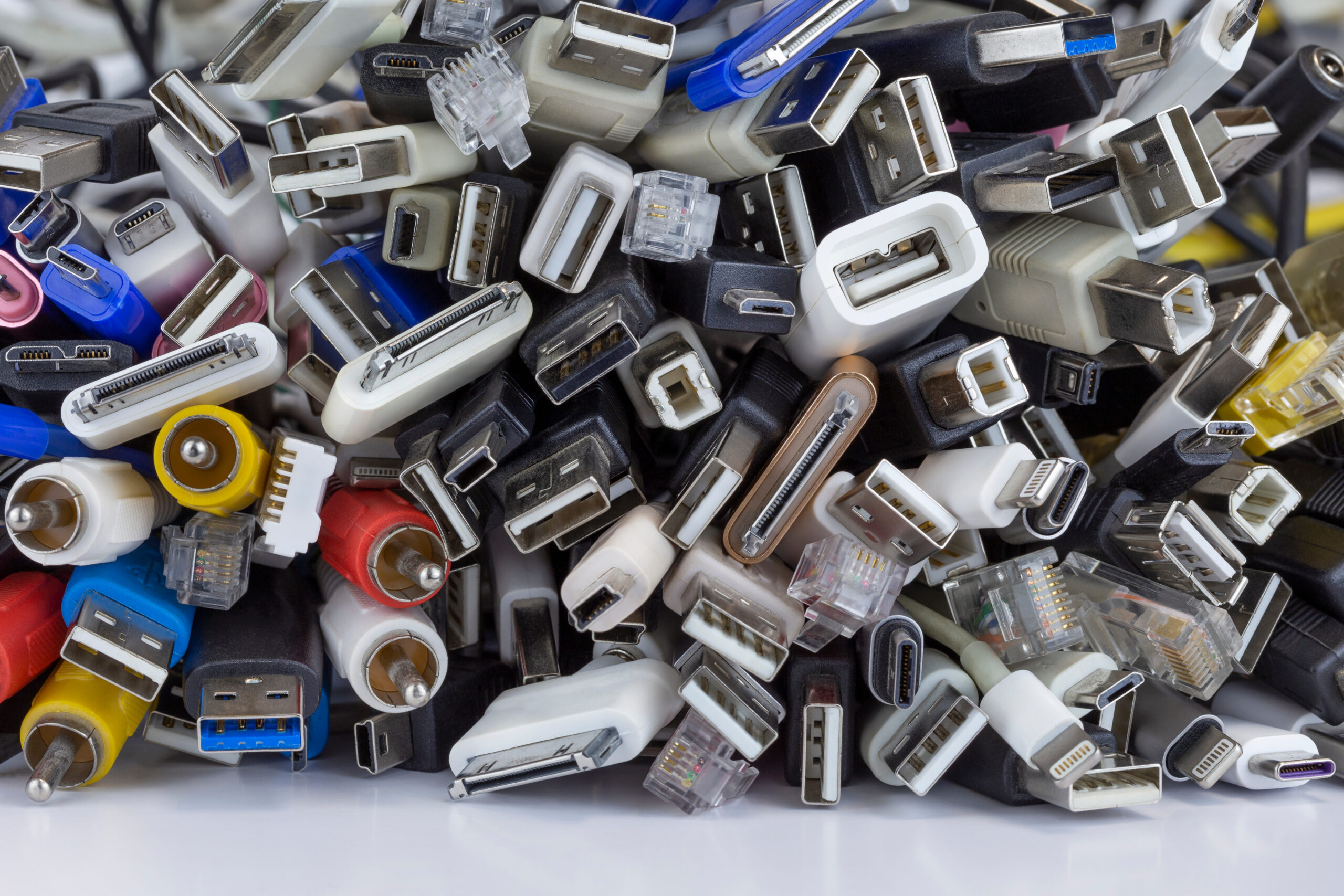
The Gemini 335Le takes the related depth platform toward industrial Gigabit Ethernet with PoE and rugged connectors. It is an example of choosing a network-node architecture for longer reach and field-oriented cabling. Its exact transport, discovery, synchronization, and SDK behavior should be taken from the current product documentation rather than inferred from the words “Gigabit Ethernet.”
The Gemini 338Lg and Gemini 338Le provide another GMSL2-versus-Ethernet pairing for applications that also prioritize challenging ambient-light conditions. The Gemini 345Lg is positioned for rugged outdoor robotics with a GMSL2/FAKRA interface and wide field of view. These models should be shortlisted by optical and environmental requirements first; interface suffixes do not make unlike sensing requirements interchangeable.
A unified application SDK can reduce API changes across interface variants, but it cannot make the transports operationally identical. Use Orbbec’s current GMSL supported-hosts and system-requirements page to identify verified camera, carrier, compute, and driver-owner combinations. Confirm the exact software release and camera count before freezing a design; a partner platform’s maximum input count is not a universal GMSL2 limit.
For early selection, compare Orbbec stereo vision cameras by sensing requirement and interface. If camera count, cable path, host, synchronization target, or environmental qualification remains uncertain, involve camera and host-platform engineering before the POC bill of materials is frozen.
Minimum POC Before Design-In
A useful POC is not a best-case demo. It is a controlled attempt to expose the failure modes that the production robot will otherwise discover for you.
- Freeze the complete topology: camera model and firmware, cable and connector, hub/switch/deserializer, carrier, compute module, OS, driver, SDK, power source, and configuration versions.
- Run the final camera count, resolution, frame rate, and stream combination. Do not extrapolate a one-camera low-load test to the production topology.
- Log frame count, corrupt or dropped frames, timestamp discontinuities, CPU and memory load, controller/NIC/CSI utilization, and interface-specific diagnostic counters.
- Measure latency and synchronization at defined boundaries, including exposure or source event, camera output, host receipt, middleware, and application consumption.
- Inject faults: interrupt power and data, restart the application, reboot the host, replace a camera, and verify recovery time, identity, configuration, and calibration mapping.
- Exercise cable length, bend and strain, vibration, power transients, temperature, and representative electromagnetic exposure at a severity appropriate to the application.
- Run a full-load soak while tracking interface metrics and end-to-end task KPIs such as navigation update rate, localization stability, obstacle detection, or manipulation cycle time.
- Define pass, investigate, and fail thresholds before testing. A threshold invented after the data arrives is a preference wearing a lab coat.
Frequently asked questions
Is GMSL2 always lower latency than USB or Ethernet?
No universal end-to-end ranking is valid. A GMSL2 transport can offer low, predictable link behavior, but exposure, readout, camera processing, host buffering, middleware, and the application still determine control-loop latency. Measure the complete path for the intended stream configuration.
Can USB cameras be used in production robots?
Yes. USB is a sound production choice when cable length, connector retention, power, controller topology, bandwidth, environment, and recovery behavior are controlled and validated. The protocol name is not the qualification plan.
Do Ethernet cameras always compress video?
No. An Ethernet implementation can transport compressed or uncompressed data and may send raw images, processed images, depth, or metadata. The camera architecture and transport protocol determine the answer.
Does GMSL2 automatically synchronize multiple cameras?
No. Multi-camera synchronization requires compatible sensors, trigger or frame-sync distribution, serializer/deserializer behavior, timestamp handling, drivers, and application logic. Ask what event is aligned and what skew was measured.
Is FAKRA the same as GMSL2?
No. FAKRA is a family of keyed automotive-style RF connectors. GMSL2 is a SerDes link technology. A system can use a FAKRA connector for a GMSL2 link, but the terms describe different layers.
Can one SDK make USB-to-GMSL2 migration seamless?
A common SDK can preserve much of the application API and reduce software migration. It cannot eliminate host-driver integration, deserializer and carrier compatibility, power, synchronization, resource allocation, cable qualification, or recovery testing.
Choose the Architecture You Can Prove
The best robot camera interface is the one that meets the perception task with the lowest validated total system risk—not the interface with the most impressive isolated number. USB often wins when simplicity and controlled proximity dominate. Ethernet often wins when distance, network serviceability, and distributed placement dominate. GMSL2 often wins when centralized multi-camera performance, harnessing, and controlled timing justify deeper integration.
Start by drawing the complete data, power, timing, and recovery path. Calculate the payload. Define the latency and synchronization boundaries. Then build the POC around the final topology and its most expensive failure modes. Once those constraints are explicit, selecting an Orbbec interface variant becomes an engineering decision rather than an exercise in translating suffixes.
Sources and Further Reading
- Analog Devices — Building High Performance Robotic Vision with GMSL
- NVIDIA — GMSL Architecture Overview
- NVIDIA — Camera Development and SIPL
- USB-IF — Cables and Connectors
- A3 — USB3 Vision Standard
- A3 — GigE Vision Standard
- Orbbec — Gemini 335Lg
- Orbbec — Gemini 335Le
- Orbbec — Gemini 338Lg
- Orbbec — Gemini 338Le
- Orbbec — Gemini 345Lg
- Orbbec Docs — GMSL Supported Hosts and System Requirements
- Orbbec — Stereo Vision Camera Comparison
Find the Right Interface for Your Robot
Compare Orbbec depth cameras by interface type and sensing requirements. Our engineering team can help you evaluate USB, Ethernet, and GMSL2 options for your specific deployment.