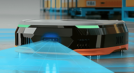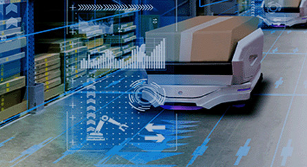
At a time when robotics, automation, and intelligent systems are becoming faster every day, precise 3D navigation is crucial. This technology allows machines to understand and interact with their environments. Today’s spatial mapping solutions rely more on the fusion between stereo vision and inertial measurement unit (IMU) data. From autonomous drones navigating dense forests to warehouse robots avoiding moving forklifts, fused IMU and stereo vision systems can provide better 3D perception and position tracking, which are becoming the backbone of reliable 3D navigation.
This comprehensive guide will cover the principles, architectures, and implementation strategies behind next-generation 3D navigation systems. Discover how combining visual and inertial data can improve accuracy and reliability, helping developers to build smarter, more versatile products.
Why Fuse Inertial and Visual Data?
Achieving reliable six-degrees-of-freedom pose estimation is a foundational challenge in robotics and autonomous vehicles. By fusing inertial and visual data, these applications combine the strengths of both for more precise positional tracking. The main objective is to determine the system’s position and orientation in a space, in real time and in changing environmental conditions. These requirements reveal the importance of strong 3D navigation and spatial mapping solutions.
Strengths of Stereo Vision
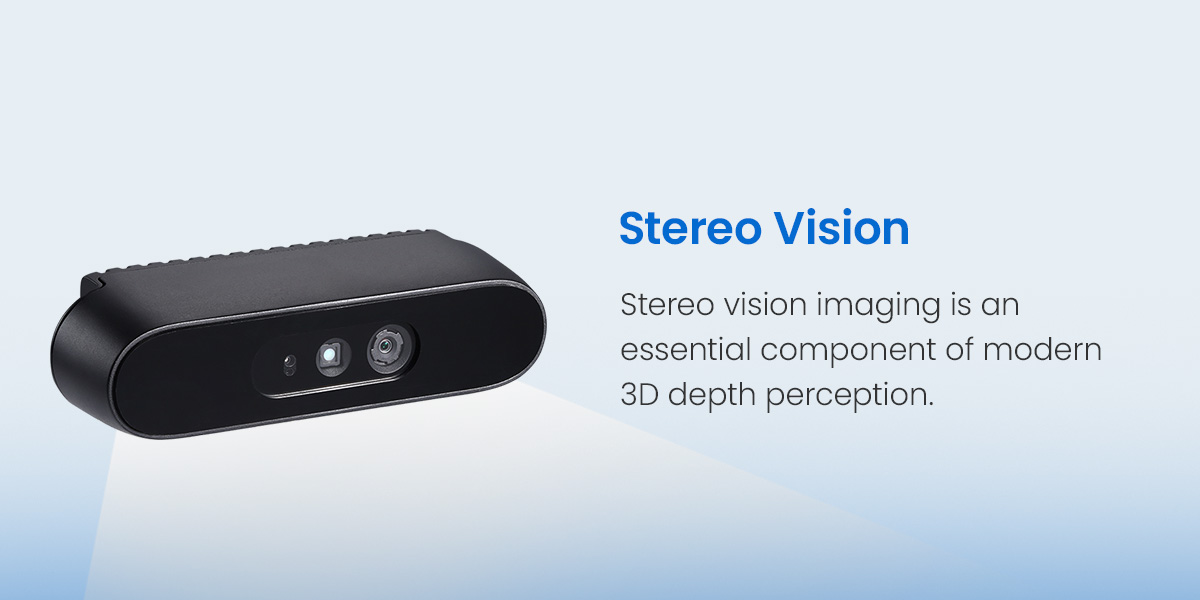
Stereo vision imaging is an essential component of modern 3D depth perception. It works by capturing synchronized images from two horizontally separated cameras, allowing a stereo system to estimate the disparities of the corresponding points in each image. With the disparity map, the stereo vision system can estimate stereo depth more accurately and provide real 3D geometry and absolute scale, which illustrates a more detailed 3D representation of the environment. This high-fidelity 3D spatial mapping is essential for tasks like obstacle avoidance, object recognition, and scene recognition. It grants the downstream systems a better understanding of the real world.
Strengths of IMU
Despite the strengths of vision-only systems, they are often insufficient in visually degraded environments. Even the most advanced stereo vision image processing algorithms can struggle with textureless surfaces, repetitive patterns, and low-light conditions, for instance. This is where IMUs come in.
IMUs provide high-frequency measurements of linear acceleration and angular velocity, enabling quick positional tracking and IMU mapping. These sensors are immune to visual ambiguities and can maintain motion estimates even during quick maneuvering or when faced with temporary visual occlusions.
The Fusion Payoff
Fusing visual and inertial data delivers a synergistic payoff. Visual data corrects for the drift that’s inherent in IMU-only systems, while inertial data fills in gaps from visual degradation. Combining them gives developers real-time mapping and more robust 3D navigation, even in the most challenging situations. The fusion of stereo vision and IMU sets a new standard for 3D spatial mapping in dynamic real-world environments.
VIO vs. Visual SLAM: Key Distinctions
When it comes to vision systems technology, it can be challenging to distinguish between visual-inertial odometry (VIO) and visual simultaneous localization and mapping (vSLAM). While both technologies use visual and inertial data, their objectives and capabilities differ.
- VIO: VIO mainly focuses on accurate, local motion tracking. It estimates a system’s trajectory over small time intervals and gives updates in real time of the system’s position and orientation. Developers can optimize VIO for responsiveness, often use it as the front-end of a larger mapping system.
- vSLAM: vSLAM, in contrast, expands upon VIO by incorporating loop closure and global map optimization. Loop closure allows the system to recognize locations it has already visited. From there, it can correct the accumulated drift and be more consistent long-term in the map. vSLAM is crucial for applications that call for persistent, large-scale mapping and navigation.
Overall, VIO delivers precise local tracking, while vSLAM ensures global map accuracy and consistency over extended trajectories.
Core Architectures for Sensor Fusion
Different architectural approaches can be used when integrating visual and inertial data, each with its own trade-offs in complexity, accuracy, and computational requirements. Loosely coupled systems are an approach where vision and IMU run as separate modules, with their outputs fused by a filter like the extended Kalman filter. In contrast, tightly coupled systems measure raw features and IMU together in one single process, and are the state-of-the-art in terms of high accuracy.
The choice between these two systems will depend on the application.
Loosely Coupled Systems
Loosely coupled systems are the most straightforward approach. In this architecture, vision and IMU subsystems operate independently, each producing its own estimates of motion. These outputs are then fused using a filter, which combines the high-frequency updates from the IMU with the lower-frequency, but more globally accurate, updates from the vision system.
While simple to implement and computationally efficient, a loosely coupled system might not be the most accurate choice, especially in situations with rapid motion and significant sensor noise. Separating the processing pipelines can also limit the system’s ability to fully take advantage of the complementary information available within the raw sensor data.
Tightly Coupled Systems
Tightly coupled systems represent the state-of-the-art in sensor fusion for 3D navigation. In these architectures, raw feature measurements from the stereo vision image processing pipeline and IMU data are joined together and optimized within a single estimation framework. Techniques like factor graphs and bundle adjustments can minimize visual reprojection errors and inertial measurement errors simultaneously.
This joint optimization makes the system more accurate and robust, and when implemented with a high-performance 3D machine vision camera, tightly coupled systems become even more effective. By leveraging the full richness of sensor data from high-performance 3D machine vision cameras, tightly coupled systems deliver enhanced accuracy and robustness — making them an optimal choice for developers working in challenging environments.
| Key Differences Between Loosely coupled Systems and Tightly Coupled Systems | ||
|---|---|---|
| Characteristics | Loosely Coupled Systems | Tightly Coupled Systems |
| Fusion level | Output-level (post-estimation) | Measurement-level (joint optimization) |
| Data used | Pose and velocity estimated from vision and IMU | Raw visual features and IMU samples |
| Accuracy and robustness | Moderate and may degrade with fast motion or noise | Advanced and resilient in challenging conditions |
| Sensor information | Limited by separate pipelines | Fully uses raw measurements from both sensors |
| Implementation complexity | Simple to implement and maintain | More complex architecture and optimization pipeline |
| Latency | Generally lower due to simple processing | May be higher from optimization but can be managed with design choices |
| Best fit | Simple applications and quick deployment | High-precision, performance-critical applications and challenging environments |
Building a Stereo-Inertial System Step-by-Step
Building a complete and robust stereo-inertial navigation system will require following specific steps, from choosing the correct hardware to implementing the right algorithms and map management systems.
Step 1: Hardware Selection and Rig Calibration
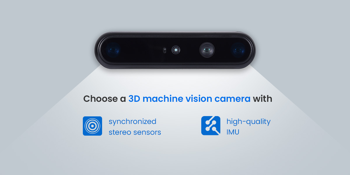
Hardware is the foundation of a high-performance system. Choosing a 3D machine vision camera with synchronized stereo sensors and a high-quality IMU is a good start. The cameras must be capable of capturing high-resolution images at sufficient frame rates, while the IMU should provide low-noise, high-frequency measurements.
Calibration supports geometric and temporal consistency so the system can deliver the highest accuracy and robustness possible. Without proper calibration, stereo depth and visual inertial estimates can become noisy, unstable, and biased, particularly during fast motion.
Follow these steps for a smooth calibration process:
- Intrinsic calibration: The first step is intrinsic calibration, which is to precisely estimate the camera’s internal parameters, like focal length, principal point, and lens distortion coefficients. An accurate intrinsic calibration ensures that the 3D points reconstructed from image pairs are metrically correct, which forms the basis for reliable stereo camera depth estimation.
- Stereo extrinsics: This involves determining the exact position and orientation, or baseline, between the two cameras. Even minor discrepancies in the baseline can cause significant inaccuracies in the overall depth perception. Calibration procedures, usually involving checkerboard patterns and optimization algorithms, are often employed to get sub-millimeter precision.
- IMU-camera extrinsics: This calibration is just as critical as the others. The transformation between the IMU and the stereo camera rig must be known with high accuracy. This way, the system can correctly interpret IMU measurements in the camera’s coordinate frame — a prerequisite for effective sensor fusion.
- Time synchronization: The final critical step of hardware setup is time synchronization. All sensor data must be timestamped at the hardware level to ensure precise temporal alignment. Even a millisecond-level discrepancy may degrade fusion algorithm performance and therefore lead to perception errors, especially in high-speed or dynamic applications.
Step 2: The Algorithmic Pipeline
After calibrating the hardware, it is important to shift focus to the algorithmic pipeline that processes and fuses the sensor data:
- IMU preintegration: This is the process of integrating high-frequency IMU measurements between visual keyframes. Rather than processing every IMU sample individually, preintegration condenses the data into a single motion constraint, which significantly reduces the computational load while maintaining its accuracy. This step is critical for maintaining real-time performance in embedded systems.
- The visual front end: The visual front end is responsible for extracting and matching features from the two stereo images. The right feature extraction algorithm can identify salient points in the images and match them across frames to estimate the motion. Stereo depth estimation can be performed by triangulating matched features, generating a dense or semi-dense 3D point cloud of the environment.
- Initialization: A critical phase, initialization is where the system estimates initial velocity, gravity direction, and IMU biases. An accurate initialization will kick-start the fusion process and ensure stable operation. This often involves stationary observance for a brief period, where the system collects enough data to resolve ambiguities.
- Joint optimization: Joint optimization is the core of the fusion process. The system constructs a cost function that incorporates visual reprojection errors, or the difference between observed and predicted feature positions and inertial measurement errors. Advanced techniques like nonlinear least squares can solve for the system’s pose, velocity, and sensor bias. The joint approach can be more effective and offer more accuracy, even in environmentally challenging applications or when sensor noise is present.
Step 3: Map Management and Loop Closure
As the system navigates its environment, it constructs a map of observed features and landmarks. With time, small errors can build up and cause drift in the estimated trajectory. Loop closure is the process the system uses to recognize when it has returned to a previously visited location. By aligning the current observations with a stored map, the system can correct the accumulated drift and maintain global consistency.
With the right map management strategies, developers can ensure their system operates continuously. Strategies like storage and retrieval of map data, as well as mechanisms for updating and refining the map as new information becomes available, can be effective. Loop closure and global optimization are hallmarks of advanced 3D navigation systems, helping with persistent and large-scale mapping in dynamic spaces.
Further Challenges and Solutions
With significant development of 3D depth perception and sensor fusion, deploying stereo-inertial systems in real-world applications still presents challenges. Analyzing the challenges can help these systems perform better in variable environments.
Handling Dynamic Environments
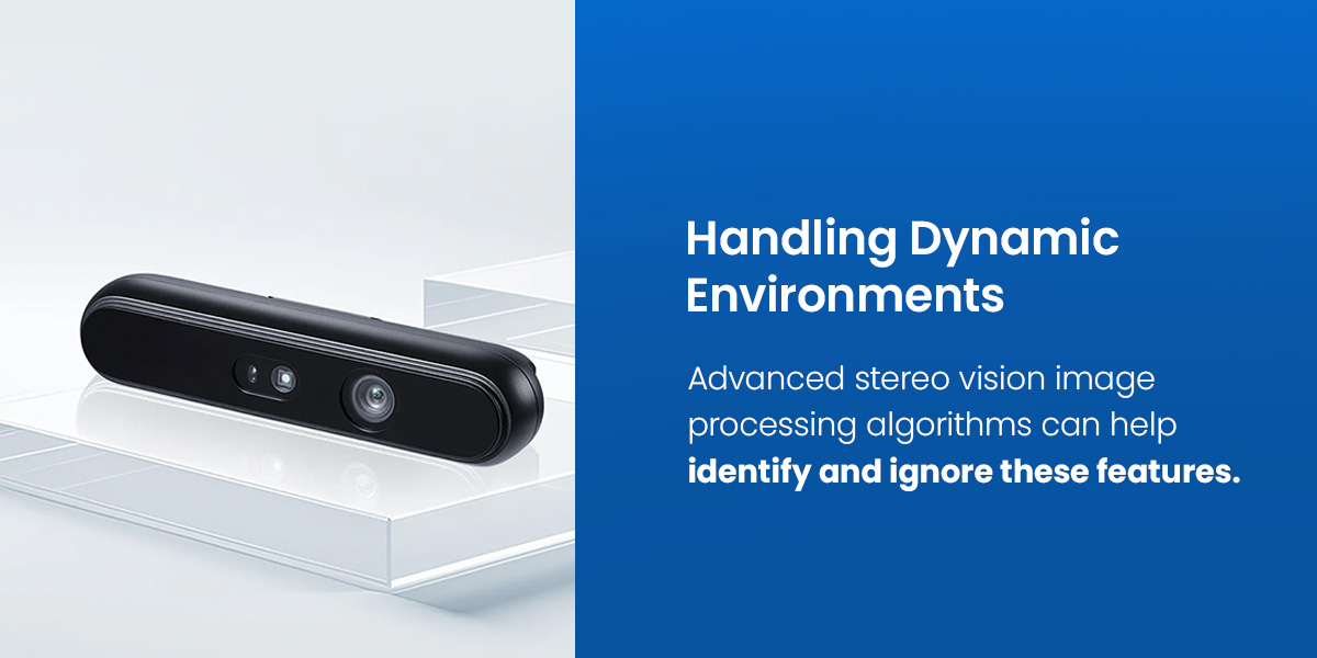
A primary challenge is the presence of dynamic objects, people, vehicles, or machinery that move independently of the system. These moving objects can introduce errors into the motion estimation process, affecting the map and its navigation performance. Advanced stereo vision image processing algorithms can help to identify and ignore these features. Techniques like motion segmentation, outlier rejection, and feature tracking can ensure only static and reliable features contribute to the pose estimation and mapping process.
Managing Computational Load
Edge devices like embedded CPUs or GPUs can operate in real time, placing strict constraints on computational resources. Essentially, there is a fundamental trade-off between performance and accuracy. Dense methods, which process every pixel in the image, can offer greater accuracy but require more computational load; Sparse methods that focus on just a subset of salient features may be more efficient but often sacrifice some detail.
Modern systems take a hybrid approach, adjusting the level of detail based on available resources and the specific task requirements. As such, quickly implementing 3D navigation and real-time mapping algorithms is crucial when deploying robotics, drones, and autonomous mobile robots (AMRs).
Ensuring Robustness
Environmental conditions like low light, motion blur, and textureless scenes can pose many challenges for vision-based systems. These conditions can cause the system to rely more on the IMU for positional tracking and IMU mapping. With adaptive sensor fusion strategies, the system can adjust the weighting of the visual and inertial data based on the quality of its observations. It can then keep operating reliably even when one modality is temporarily degraded.
Benchmarking and Evaluating Performance
Evaluating the performance of stereo-inertial navigation systems requires a designed benchmarking process. Several standardized datasets were created for this purpose. These datasets provide synchronized stereo and IMU data, along with ground-truth trajectories, for an objective comparison of different algorithms and systems.
Key accuracy metrics include absolute trajectory error (ATE) and relative pose error (RPE). ATE measures the estimated trajectory’s overall deviation from the ground truth, providing a global assessment of system performance. RPE evaluates the trajectory’s local consistency over short intervals, highlighting the system’s ability to maintain accurate motion estimates in real time.
Best practices for real-world testing involve varying the motion profile, lighting conditions, and scene types. This ensures a robust system that can handle the full spectrum of challenges encountered in practical applications. Comprehensive evaluation across all types of scenarios is crucial for validating the system’s overall reliability and generalizability.
Accelerate Your Project With Orbbec 3D

Fusing stereo vision and IMU data enables developers to achieve new levels of spatial mapping, tracking, and reliability. For applications ranging from drones in forests to warehouse robots, dependable 3D navigation is being built upon fused IMU and stereo vision systems.
Orbbec’s 3D machine vision cameras, such as the Gemini 2, are engineered for seamless sensor integration, with factory calibration and hardware synchronization that eliminate the major sources of error and accelerate the development process.
Since 2013, Orbbec has been on a mission to democratize 3D vision technology, delivering smart products with exceptional performance and value. Orbbec provides 3D stereo and IMU-enabled 3D machine vision cameras, SDKs, and integration guides to make implementation as smooth as possible. You are sure to find the ideal camera for your robotics, drone, or AMR project.
Orbbec 3D Vision Experts are ready to support your project from design to deployment. Contact us to consult about products or ODM/OEM services.