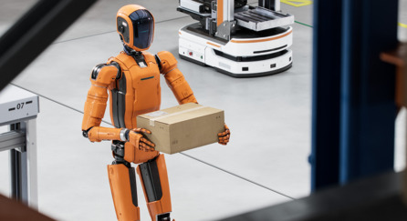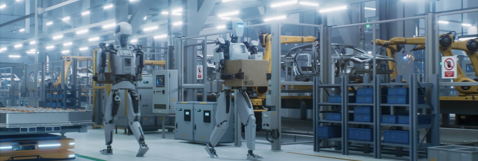
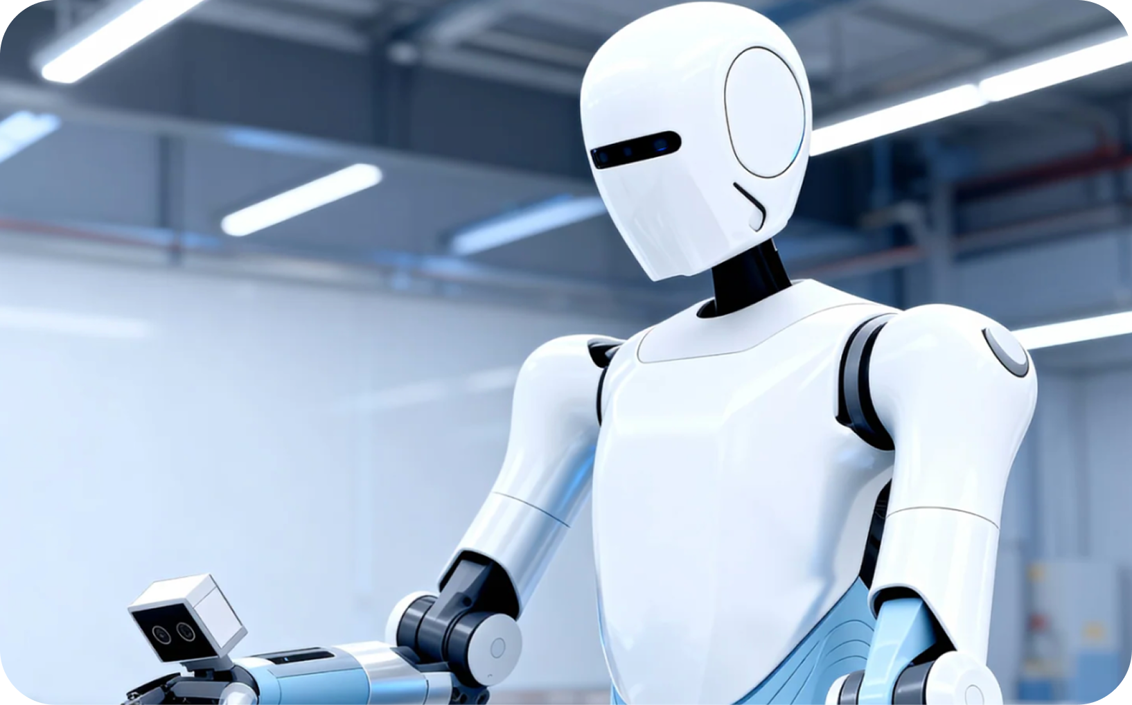
Imagine a humanoid robot retrieving a container from a shelf, carrying it across a room, and placing it on a workbench. The first question is what the robot needs to observe at each stage. A camera that sees the entire shelf may lose the target behind an approaching hand. A useful forward view may become blocked by the container during transport.
Designing 3D vision for humanoid robots means connecting those changing observations to decisions and physical actions. Camera placement, calibration, perception software, robot state, and motion control have to agree about what the robot sees and when it saw it. More cameras or a larger model can help only when the surrounding architecture can use their outputs.
This guide uses that hypothetical retrieval task to connect the major design decisions. For project leaders, the result is a way to define a feasible first milestone. For developers, it is a map of software interfaces, research directions, and experiments to investigate.
Start with the job and its failure conditions
“Pick and carry a container” contains several distinct problems. The robot must approach a workable position, identify the correct object, estimate where to reach, establish a grasp, move with the payload, and verify placement. Each stage changes the required view and the meaning of success.
Write the first deployment envelope before choosing sensors: object sizes and materials, shelf geometry, lighting, floor conditions, allowed human assistance, and the robot configurations used during the task. Include recovery. If a failed grasp requires an operator to reset the system, that intervention belongs in the operating model.
Use a small set of acceptance measures across the entire task:
- Completion rate, with success and failure recorded separately for approach, grasp, transport, and placement.
- Cycle time including retries and recovery, alongside interventions per attempted task.
- Target visibility and usable depth in the regions required for each action.
- Observation age when a decision is made, measured under the expected compute load.
- Placement or grasp error relative to the task tolerance, with contact outcomes recorded where relevant.
Agree on thresholds for the application before testing. A controlled demonstration can establish feasibility; repeated trials across the declared operating envelope establish how far that evidence extends. Neither a sensor specification nor a single successful run supplies that answer.
Give each camera position an observation job
Humanoid robot camera placement is a coverage problem across motion. Evaluate the arms, hands, carried objects, and body in their working poses. A view that is clear with the robot standing still may disappear while reaching, turning, or bending.
| Viewpoint | Useful observation role | Constraint to investigate |
|---|---|---|
| Head | Survey the workspace, locate targets, and support an operator’s view. | Gaze changes the camera pose and coverage. Looking toward a hand can reduce the forward view. |
| Chest or torso | Observe a working volume from a body-mounted perspective. | Arms and payloads can block the view. A fixed torso mount still moves relative to the world. |
| Wrist or end effector | Observe local geometry as the hand approaches an object. | The gripper can occlude the target; working distance, added mass, motion, and cable routing matter. |
| Additional rear or downward views | Cover a task-specific blind region, such as travel with a payload. | Add only with an identified consumer and coverage need; each view adds integration and compute work. |
For the shelf task, a body view can establish context while a wrist view supports the final approach. Define the handoff: how are observations related in a common frame, what happens if estimates disagree, and which view remains available after the gripper closes? The answer may include moving the head or changing the approach pose before adding another sensor.
Orbbec’s Gemini 305 and 305g are product starting points for investigating wrist-mounted, close-range observation. The Gemini 330 Series offers other stereo-camera configurations and interface variants to evaluate against body-view requirements. These are candidate roles to test; an installation position alone does not determine the right model.
For a different imaging direction, Orbbec’s Physis announcement introduces the 257g RGB stereo camera and 157g monocular RGB camera for humanoids and other embodied AI applications. The distinction matters architecturally: determine where depth is produced, which RGB views the application consumes, and what host resources are required. Confirm the documented integration path for the chosen configuration before planning around it.
Research also makes coverage a system variable. RPL studies humanoid locomotion using depth observations and body state, with explicit treatment of self-occlusion and imperfect depth. It is a useful research entry for evaluating views along motion, rather than treating a stationary field-of-view sketch as sufficient evidence.
Connect observations to action
The following reference pattern makes the handoffs visible. A project may use explicit geometry, a learned policy, or both. The boxes describe responsibilities that the integration must resolve; they do not prescribe a single software stack.
The important design artifact is the contract at each handoff. A detector may produce an object label and image region. A geometric estimator may produce an object pose, frame, timestamp, and quality indicator. A policy may produce end-effector targets or joint actions with a particular horizon. The receiving component must understand those outputs and recognize when they are unusable.
For retrieval, recognizing “the blue container” is one contract; obtaining a reachable grasp target is another. The execution system also needs the robot’s current state and constraints. Vision helps determine where to act, while joint, inertial, force, or tactile observations can help determine what happens during contact. Research such as EyeSight Hand explores the contribution of tactile sensing to manipulation; the appropriate feedback depends on the task.
Preserve coordinates and time through every handoff
A depth value becomes actionable only with the camera model, depth scale, and coordinate relationship needed to interpret it. For a wrist camera, the mount calibration describes its relationship to the wrist link. The arm configuration determines where that link was relative to the robot when the image was captured. Head and torso observations require the same attention to changing body pose. The resulting camera pose highly depends on the accuracy of the robot’s kinematic model and joint-state estimate; structural compliance or mounting deflection can introduce additional extrinsic error. ROS tf2 is an entry point for managing transforms over time. When combining observations, preserve capture timestamps and document the relationship between device clocks and the robot’s time base. Pairing an old image with the newest joint state can move an apparently well-detected object to the wrong location.
Alignment between color and depth, exposure synchronization between cameras, and conversion into a robot frame solve different problems. Verify each one that the application requires. Factory camera calibration and SDK output do not establish the accuracy of a complete mounted robot system.
Identify what consumes each data stream
An explicit pipeline might combine object detection, geometric localization, a planning scene, and motion planning. A learned policy may map configured images and robot state to actions. Hybrid designs can use learned semantics alongside geometric reasoning, planning, or independent execution monitoring.
NVIDIA’s GR00T data configuration makes the interface work concrete: it defines video, state, action, and language modalities, observation histories, and action representations. Check the selected model and embodiment configuration. The presence of a depth camera does not mean a vision-language-action (VLA) policy consumes depth, and an action tensor is useful only when its representation matches the robot interface.
The OKAMI research system provides a useful hybrid example. It combines RGB-D demonstrations, task interpretation, object localization, motion retargeting, and learning from collected trajectories. Its reported scope focuses on upper-body manipulation; it should be read as a research direction, not evidence that an arbitrary humanoid can perform the full mobile retrieval task.
Choose tools by their inputs and outputs
A useful toolchain names the data crossing each boundary and the work still owned by the robot team. These official entry points illustrate different layers. They are not a claim that every combination below has been validated together.
| Development entry | Input and useful output | Integration boundary |
|---|---|---|
| Orbbec SDK v2 and ROS 2 wrapper | Supported cameras → configured streams, camera data, and ROS integration. | Check model, firmware, OS, host, and wrapper support together. Acquisition is the first layer. |
| ROS tf2 | Frame relationships over time → transforms between camera and robot frames. | Supply and validate calibration and robot-state timing; the framework does not measure mounting error. |
| MoveIt Planning Scene Monitor | Robot state, transforms, collision objects, and depth or point clouds → an updated planning scene. | Configure geometry and self-filtering. This does not supply humanoid balance or contact control. |
| Isaac ROS nvblox | Depth and estimated pose → local 3D reconstruction and navigation costmap outputs. | Provide localization and choose the mapping mode. A Nav2 costmap does not supply humanoid footstep control. |
| GR00T data configuration | Defined observations and embodiment interfaces → model-ready data and interpretable action outputs. | Match views, histories, state and action conventions; investigate training and deployment requirements. |
For example, MoveIt’s planning-scene documentation shows why adding a point cloud is only part of collision reasoning: the scene also tracks robot state and transforms, and depth updates can remove the robot’s own geometry. A bad body model or mistimed state can therefore become a perception problem downstream.
Similarly, nvblox illustrates a path from depth and pose to a spatial representation used by navigation. Its static and dynamic processing assumptions must match the environment. For a walking robot, the team still needs a route from that representation to locomotion decisions and the platform’s whole-body controller.
Budget latency across the complete behavior
Camera frame rate describes only one stage. Exposure, transport, depth processing, buffering, model inference, planning, and command delivery all contribute to the age of information used for an action. Different consumers can also require different update schedules.
Measure that chain on the intended host with the expected streams and workloads active. Record acquisition, host arrival, perception completion, and action issue times in a documented time base. Report the distribution, including the tail, and count dropped or rejected observations. A smooth preview is not a timing measurement.
Then decide what happens when information is late. During the final approach, the system may need to reacquire a target or suspend the next task transition. The robot-specific controller must define how it maintains a stable, appropriate execution state; a generic “stop” instruction is not a complete humanoid control design.
Interface selection belongs in this budget because it changes the host connection, routing, power, and integration work. Use the USB, Ethernet, and GMSL2 architecture guide for that decision, then validate the selected camera, connection, host, and software as one configuration.
Build evidence in three integration stages
A staged proof of concept (POC) reduces the number of interacting unknowns. Keep the task and acceptance measures consistent as complexity increases, so the team can identify what changed when performance declines.
| Stage | Experiment | Evidence needed to advance |
|---|---|---|
| 1. Observe the task | Record candidate views through the intended body, arm, and payload poses before attempting autonomous execution. | Coverage, usable depth, coordinate consistency, timestamps, and visibility failures are understood. |
| 2. Manipulate in a constrained setup | Run approach, grasp, and placement with controlled objects and a supported or stationary platform, as appropriate. | Repeatable task results, execution limits, failure detection, and recovery are demonstrated. |
| 3. Combine mobility and manipulation | Add body motion, changing light, payload occlusion, compute contention, and the required route. | Results remain within the agreed envelope; failures can be attributed and recovered from as designed. |
Save synchronized observations, robot states, actions, and task outcomes from the beginning. Keep evaluation scenes separate from tuning or training data. When a grasp fails, ask whether the object was invisible, depth was unusable, coordinates were wrong, the planned motion was unsuitable, or contact differed from expectations. “The AI failed” is too broad to guide the next experiment.
Simulation can explore layouts, motions, and failure cases before hardware trials. The RPL work, for example, models depth delay, noise, dropout, and self-occlusion. These are useful categories for a test plan, while real objects, lighting, cabling, and contact still require physical validation.
The deliverable from each stage should be a reproducible configuration and evidence package: camera placement, stream settings, calibration versions, host and software versions, trial conditions, metrics, and representative failure recordings. This gives a decision maker a concrete basis for funding the next stage and gives engineers a starting point for investigation.
Turn the POC into an integration plan
Once the task is repeatable, document ownership across the camera, host, perception, robot platform, and application. Define what changes require recalibration or revalidation, including a replacement mount, firmware update, camera substitution, or new policy. Confirm access to the information needed to diagnose failures in deployment.
Orbbec can enter that process through standard cameras, SDK access, and scoped hardware or vision-integration support. Where a project needs contract manufacturing (CM) or joint design manufacturing (JDM), discuss the hardware, calibration, validation, and production responsibilities explicitly. The robot team’s task algorithms, control architecture, and system acceptance remain defined project responsibilities.
To start a camera evaluation, explore the Gemini 330 Series alongside the near-field requirements identified earlier. For an integration discussion, contact Orbbec with the task sequence, candidate camera positions, operating distances, host, interface constraints, and early test recordings. That information connects a product conversation to an engineering decision.
The next article examines wrist vision in more detail: maintaining a useful view near the gripper, handling occlusion and motion, and connecting close-range observations to manipulation.
Frequently asked questions
How many cameras does a humanoid robot need?
There is no universal count. Map required observations through the full task, including body motion and payload occlusion. Add a view when it closes an identified coverage gap and the software can use it. Evaluate the resulting calibration, timing, compute, and mechanical costs.
Does every humanoid VLA model use depth?
No. Inputs depend on the selected model and embodiment configuration. RGB video and robot state may be the policy inputs, while depth supports another component such as localization, geometric checking, or data preparation. Name that consumer before adding a stream to the architecture.
Can a depth camera and ROS provide a complete humanoid stack?
They provide building blocks for sensing and integration. Task logic, state estimation, motion generation, execution control, and validation still need to be assembled for the robot and application. A navigation map or manipulation planner does not by itself establish walking balance or contact behavior.
Sources
- Orbbec Gemini 305 Product Page: orbbec.com/products/stereo-vision-camera/gemini-305/
- Orbbec Gemini 305g Product Page: orbbec.com/products/stereo-vision-camera/gemini-305g/
- Orbbec Gemini 330 Series: orbbec.com/products/stereo-vision-camera/gemini-330-series/
- Orbbec Physis RGB Camera Announcement: orbbec.com/news/orbbec-announces-physis-rgb-cameras-for-humanoid-robots-and-embodied-ai/
- Orbbec SDK v2 for Developers: orbbec.com/developers/orbbec-sdk/
- OrbbecSDK ROS 2 Wrapper (GitHub): github.com/orbbec/OrbbecSDK_ROS2
- ROS tf2 Documentation: docs.ros.org/en/jazzy/Concepts/Intermediate/About-Tf2.html
- MoveIt Planning Scene Monitor: moveit.picknik.ai/main/doc/concepts/planning_scene_monitor.html
- Isaac ROS nvblox: nvidia-isaac-ros.github.io/repositories_and_packages/isaac_ros_nvblox/
- NVIDIA GR00T Data Configuration: docs.nvidia.com/isaac/doc/data_format.html
- RPL (Robot Perception Learning): robot-perception-learning.github.io/
- OKAMI Embodied AI Research: okami-embodied.github.io/
- EyeSight Hand (Meta AI Research): ai.meta.com/research/publications/eyesight-hand/