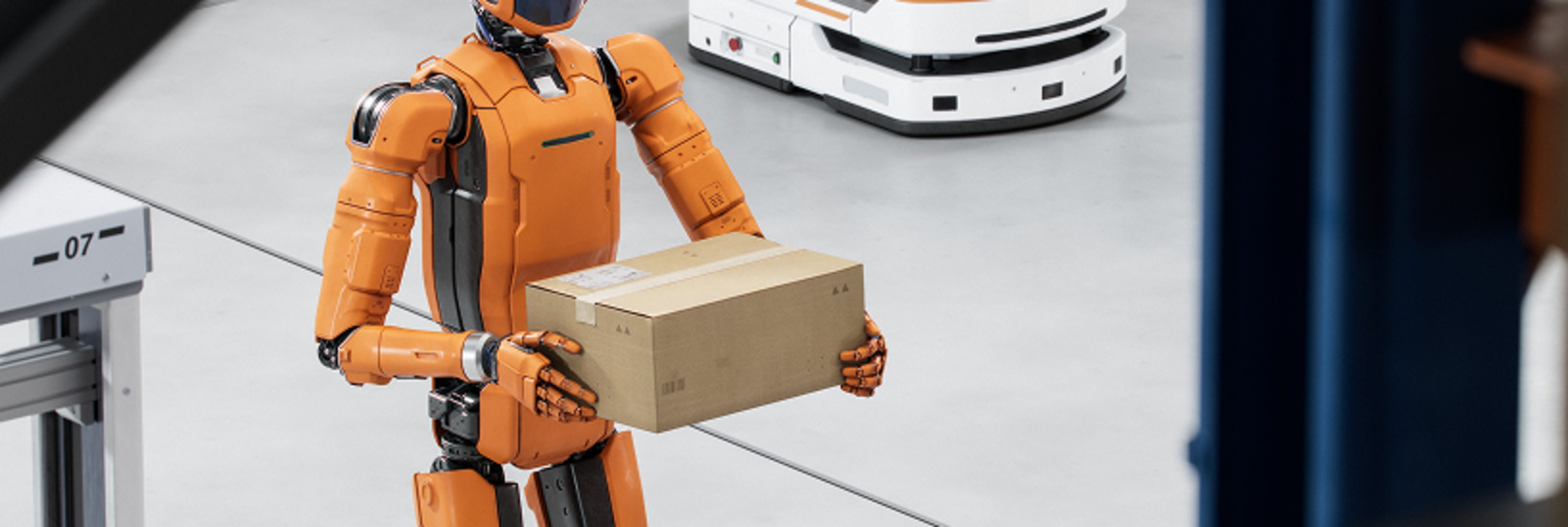
A camera shortlist becomes useful when it explains what the robot can do, under which conditions, and what still needs to be proved. For a GMSL2 depth camera, that means evaluating the optics, mounting position, host platform, simultaneous streams, and perception pipeline together.
This guide assumes GMSL2 is a plausible architecture for your robot. If you are still choosing the transport, start with the USB, Ethernet, and GMSL2 interface selection guide. Here, the goal is to turn a sensing requirement into a practical proof of concept and a defensible design-in decision.
For decision makers: the deliverable is a supported configuration, an estimate of the remaining engineering work, and evidence that the critical tasks meet their acceptance criteria. For developers: it is a repeatable dataset and test method that reveal where geometry, timing, processing, or integration limits the application.
Define the task before building the shortlist
Start with one sentence about the required behavior: detect a specified obstacle before it enters the stopping envelope, locate a bin for approach, or estimate an object pose accurately enough for the gripper. Then work backward to the information the camera must provide. A general request for high accuracy or outdoor performance is too broad to test.
Write a brief operating envelope before ordering evaluation hardware:
- Geometry: nearest and farthest required target, smallest relevant feature, camera pose, available mounting volume, and regions hidden by the robot or gripper.
- Scene: actual materials, texture, reflections, illumination directions, moving objects, robot speed, and changes between operating areas.
- Data and timing: required depth, color, infrared, and metadata streams; update rate; permitted data age; and whether observations must be aligned across cameras.
- Integration and operations: compute location, camera count, cable route, power and thermal limits, cleaning or ingress exposure, replacement procedure, and who owns support.
Separate requirements that can eliminate a candidate from preferences that can be traded. If a camera cannot see the required near-field target from its mounting position, a lower unit price does not repair the geometry. If two candidates meet the task, installation effort, compute load, supply continuity, and service costs can decide between them.
Define the task region of interest, or ROI, before testing. Keep separate regions for important edges, near-field hazards, or grasp surfaces. A high average score across the whole image can hide a failure exactly where the robot needs reliable data.
Read specifications as operating conditions
Working range, recommended or ideal range, and usable task range answer different questions. The first describes a published capability envelope; the second offers a starting region for evaluation; the third is what your application actually demonstrates. Field of view also needs context: depth and color coverage can differ, and usable stereo overlap changes with range, image profile, and alignment settings.
Avoid combining the best numbers from different modes. In the Gemini 330 Series GMSL datasheet, the 335Lg and 338Lg minimum of 0.17 m is associated with 424 × 240 resolution and a 128-disparity setting. At 1280 × 800, the listed minimum is 0.25 m with 256 disparity. Those are different operating points, not a single high-resolution, minimum-distance mode.
The Gemini 305g datasheet similarly ties its public 4 cm minimum-range claim to an 848 × 530, 256-disparity configuration. For close manipulation, verify the target area that remains usable at that distance, the available output profile, lighting, and texture. Measuring one patch of depth near the minimum range does not establish complete gripper coverage.
Also distinguish depth behavior from the color image used by the algorithm. A detector, pose estimator, or color-to-depth association may be sensitive to RGB motion distortion even when the depth imagers use global shutters. Include the actual RGB stream in dynamic tests whenever the application consumes it.
Build an Orbbec shortlist around the sensing job
The following models provide different starting points for GMSL2 robotics evaluation. Their listed ideal ranges are shortlist guidance, not task-level acceptance guarantees. Choose the candidate that matches the required scene, then test the complete configuration.
Table 1. GMSL2 camera candidates for robotics evaluation
| Candidate | Evaluation starting point | Difference to validate |
|---|---|---|
| Gemini 335Lg | General robotics baseline; listed ideal range 0.25-6 m. | Global-shutter RGB and depth; verify near-field coverage and the selected depth profile. |
| Gemini 338Lg | A comparison candidate when site illumination affects the 335Lg evaluation; ideal range 0.25-6 m. | 850 nm narrowband IR filtering differs from 335Lg. Compare both under the actual lighting and materials. |
| Gemini 345Lg | Broader coverage or demanding enclosure conditions; ideal range 0.3-6 m. | Wide and Standard depth modes; published IP67. Color uses a rolling shutter, so test RGB motion behavior. |
| Gemini 305g | Close manipulation or wrist placement; ideal range 7-50 cm. | Compact passive RGB stereo; texture, lighting, wrist load, cable clearance, and near-field coverage need testing. |
Use the 335Lg and 338Lg datasheet, 345Lg datasheet, and 305g datasheet to check the conditions behind each entry. Environmental ratings apply to the specified camera assembly and installation conditions. Verify the selected frame rate, disparity mode, connector sealing, and enclosure assumptions against the relevant limits.
The 338Lg is a useful A/B candidate when ambient light is a problem, but a filter specification alone cannot establish superiority across every outdoor scene. Likewise, the 345Lg’s wider mode may improve coverage while changing the pixel density on a small object. The evaluation should expose that trade-off in the task ROI.
For a wrist installation, use the 305g’s own mechanical specification. It is listed at 42 × 42 × 40 mm and 116 g ±10 g; do not substitute the USB Gemini 305’s mass or housing depth when calculating the 305g’s wrist load and clearance. Include the bracket and moving cable in the wrist-load calculation.
Select the host and processing path with the camera
The POC bill of materials should identify a complete combination: camera and firmware, cable assembly, power path, deserializer board, compute module and carrier, operating-system image, JetPack or BSP release, camera driver, SDK, and middleware. Add every stream’s resolution, frame rate, and pixel format. This is the configuration you will reproduce when a result is questioned.
Orbbec’s GMSL supported-host matrix separates developer kits, turnkey systems, and modular stacks. A Jetson developer kit with a documented GMSL board can provide an evaluation starting point; a partner system may offer an integrated enclosure and a different support owner. Choose with the intended deployment and support arrangement in mind, and confirm the exact board and software release.
A supported camera count does not guarantee every simultaneous stream set. The platform-driver documentation describes shared stream limits and conflicts on paired deserializer inputs. A pair of cameras that works with depth alone may not support the same configuration after RGB and infrared are enabled. Confirm the full stream set before interpreting an application failure as a camera-quality problem.
Use Orbbec SDK v2 for supported camera access, configuration, and capture. If the robot uses ROS 2, check the model-specific launch and support information in the Orbbec ROS 2 documentation. Freeze the camera intrinsics, depth scale, color-to-depth alignment choices, and camera-to-robot transforms with the dataset.
Trace the data to the algorithm that consumes it. For obstacle perception, inspect depth-to-point-cloud conversion, transforms into the robot frame, ground filtering, and obstacle extraction. For manipulation, inspect the color detection or segmentation, depth association, pose estimate, and hand-eye calibration. Record intermediate outputs. This makes it possible to distinguish missing depth from a transform error or an algorithm threshold that rejects useful data.
Create a reproducible depth quality baseline
Begin with the target GMSL2 host and SDK configuration. A USB capture can help isolate an optical issue, but it does not validate the production transport. Save baseline depth output with its processing settings documented, and a second output using the intended deployment filters. Do not label ordinary SDK depth output as raw sensor data; depth may already include onboard computation or other processing.
Use a stable, matte planar target with independently established geometry and enough visible texture for passive stereo. Record any projected texture or onboard emitter use, then repeat at representative distances and image locations. Reference measurements must use the documented depth origin and the same distance definition as the metric. Measuring from the front of the enclosure can introduce a systematic offset.
Account for reference-target flatness, alignment, positioning, instrument uncertainty, and temperature. NIST’s traceability guidance explains why a traceable measurement alone does not establish suitability for a particular use. If reference uncertainty could change a borderline pass into a fail, improve the reference or retain the result for investigation.
Orbbec’s depth-quality definitions distinguish accuracy, spatial precision, temporal precision, and fill rate. The test report should preserve those distinctions. The following is a proposed reporting scheme, not a claim that every statistic matches a vendor tool’s implementation.
Table 2. Depth quality metrics and reporting
| Metric | What to report | What it cannot establish |
|---|---|---|
| Depth error | Signed bias and a high percentile of absolute error against independent reference geometry. State units and distance definition. | A low central bias can still hide large local errors. |
| Plane residual | RMS distance to a fitted plane, with the fitting and exclusion rules recorded. | A smooth plane at the wrong distance can have a small residual. |
| Temporal variation | Per-pixel variation across a stationary sequence; report its distribution and valid-sample rule. | Low jitter alone does not prove accuracy or good motion behavior. |
| Fill rate | Valid depth pixels divided by all pixels in the predefined ROI. Report missing regions separately. | A valid value can still be incorrect; density is not correctness. |
Depth error and fill rate should be interpreted together. A configuration should not appear more accurate simply because difficult pixels have been invalidated.
For task comparisons, define the ROI in the physical scene and map it into each camera image, recording its pixel boundaries for each profile. Keep standardized image-percentage ROIs separate from task ROIs. Freeze both before inspecting results, along with the invalid-depth definition and outlier rules. Pixels with too few valid temporal samples are unevaluated, not zero-noise pixels. Preserve maps as well as summary statistics so an edge failure cannot disappear into an average.
The public DepthQualityTool release provides an additional entry point for supported configurations. Verify support for the exact camera, connection, and operating system before planning around it. Measurements from the intended GMSL2 path can instead be captured through the SDK and analyzed offline with a versioned script and the metric definitions above.
Filters belong in the experiment. Orbbec’s filter reference describes neighborhood-based hole filling, historical-frame temporal filtering, and removal filters that can discard depth. Compare baseline and deployment outputs for edge retention, missing data, false surfaces, and motion trails. A smoother image can improve one metric while reducing the information a gripper or obstacle detector needs.
Test the operating envelope and the complete application
A flat target establishes a useful baseline. The next tests should challenge the conditions that drive the purchase decision. Use actual objects and installation geometry, then run the intended camera count and application workload. The matrix below is an engineering test plan to adapt, not a universal qualification standard.
Table 3. Operating envelope test matrix
| Test | Exercise | Decision evidence |
|---|---|---|
| Coverage and materials | Near, typical, and far task positions; image edges; dark, reflective, low-texture, and thin targets. | Task ROI coverage, error and invalid-depth maps, and failures grouped by object and condition. |
| Light and motion | Expected illumination directions and transitions; static scenes and realistic robot or object motion. | Task detection or pose results, missed targets, RGB distortion, depth artifacts, and filter trails. |
| Timing and load | All required streams, camera count, alignment, point clouds, inference, and recording if used in deployment. | Per-stream FPS and gaps, data-age distribution, inter-camera skew, resource use, and task update rate. |
| Mechanical and thermal | Installed bracket, intended cable route and bend conditions, representative vibration, cold start, and operating temperature. | Changes in geometry, calibration, continuity, and task results; documented test severity and duration. |
| Recovery and replacement | Approved power or link interruption procedures; application restart, host reboot, and camera replacement. | Recovery time, correct camera identity and calibration, settings restored, and rejection of stale data. |
Give each critical scene its own result. A camera that succeeds on nineteen easy objects and fails on one essential part has not met the requirement through averaging. Report repetitions and test duration, retain failures, and distinguish repeated frames from independent runs or different camera units.
The application should expose its own acceptance measures: missed detections and false positives by scene, pose or dimensional error, successful task attempts, processing time, and recovery behavior. Define the denominator for each rate. Record the algorithm and parameter versions so a later software improvement is not incorrectly attributed to a hardware change.
Pay particular attention to data age. Establish what each timestamp means and which clock produced it before subtracting values. Orbbec’s metadata documentation illustrates different timestamp meanings; do not assume an exposure-midpoint definition applies to every model and firmware. When clocks cannot be mapped reliably, report the specific host-side interval you can measure.
For multiple cameras, capture skew and application delivery latency are separate measurements. The 335Lg synchronization guide and GMSL timing tools provide model-specific starting points. Measure a common dynamic event under the target configuration; callbacks arriving together do not prove aligned exposures. Report relevant percentiles, the observed maximum, and test conditions. The maximum observed in a test is not a guaranteed future bound.
Illustrative budget, not measured camera performance: an object moving laterally at 0.5 m/s travels 5 mm in 10 ms. If a project allocates 5 mm of apparent position error to inter-camera capture skew, that simple constant-speed model suggests a 10 ms skew budget. Exposure duration, acceleration, calibration, depth error, and application latency still need separate treatment.
Use the evidence to decide what to buy or change
Consider a hypothetical mobile manipulator with a forward-looking task at 0.5-4 m and a wrist task at 0.1-0.4 m. These are example requirements, not camera test results. The forward view might start with 335Lg and 338Lg if illumination is the differentiating condition; a wide-coverage or enclosure requirement could bring 345Lg into the shortlist. The wrist view could start with 305g, subject to texture, illumination, and mechanical testing.
If wrist occlusion prevents the needed observation, first reconsider mounting position or task sequence. If geometry is adequate but data is stale under inference load, examine the host and processing path. If real materials remain unobservable, reconsider illumination, sensing approach, or the task itself. The useful outcome of a POC is knowing which change addresses the failure, including when to remove a camera from consideration.
Assign pass, investigate, and fail criteria before running the tests. Use the task’s error and timing budgets, required operating conditions, and measurement uncertainty; there is no universal camera acceptance percentage or soak duration.
Table 4. Decision framework for camera evaluation
| Decision | Evidence required | Next action |
|---|---|---|
| Pass for the next stage | All critical scenarios meet the defined gates on the recorded configuration, with remaining risks explicitly bounded. | Freeze the evaluated baseline and proceed to the next pilot or qualification stage. |
| Investigate | A result is borderline, reference uncertainty matters, or a specific configuration or integration gap is unresolved. | Name the hypothesis, owner, configuration change, and focused retest needed. |
| Fail for this task | A critical requirement remains unmet within the allowed installation, compute, cost, or schedule constraints. | Change the architecture or shortlist; retain the failure evidence. |
For the purchasing decision, compare the camera with its required board, host, cables, fixtures, integration work, qualification, spares, and field-service effort. Confirm availability, change-notification practices, software maintenance, and support ownership with the relevant suppliers. A passing POC supports the next stage; it does not replace production qualification or the robot’s separate safety assessment.
Start the evaluation with a package engineering can use
Choose two candidates with a clear reason for comparing them. Select a documented host path, reproduce one supported depth profile, capture the hardest required scene, and add the application’s remaining streams and processing. This sequence gives an early answer about the expensive uncertainty before a larger test campaign.
Keep a small evidence package that another engineer can reproduce:
- The task and installation sketch, operating envelope, acceptance thresholds, and why each candidate was shortlisted.
- The complete hardware and software configuration, camera settings, calibration files, and simultaneous stream profiles.
- Representative captures and failure clips, evaluation scripts or commands, metric definitions, and per-condition results.
- The decision, unresolved issues, support owner, and the exact configuration changes that require a retest.
Use the linked Orbbec product pages to compare candidates, then the supported-host matrix and GMSL quick-start guide to assemble the evaluation path. Contact Orbbec with the evidence package to discuss camera selection and the remaining integration questions.
Where a robotics or intelligent-vision program needs additional vision-hardware integration, calibration, validation, or production support, ask whether a scoped JDM or CM engagement fits the identified gaps. Define responsibilities for the application algorithms and the rest of the product explicitly during that discussion.
Frequently asked questions
Which GMSL2 depth camera is best for robotics?
Choose by the required task, scene, mounting position, and supported host configuration. The 335Lg, 338Lg, 345Lg, and 305g offer different evaluation starting points. Select with results from the task ROI and application workload, then compare total deployment cost.
Can maximum resolution and minimum range be used together?
Only when the datasheet supports that exact operating point. Minimum range can depend on resolution, disparity settings, and mode. Check the simultaneous profile and verify usable coverage at the required distance.
Is a denser point cloud always better?
No. Added or retained points can contain errors, while smoothing can change edges and dynamic behavior. Evaluate accuracy, coverage, and task output together, preserving a baseline capture and the deployed processing settings.
Does a supported host configuration complete validation?
It establishes an integration starting point. The final simultaneous stream set, camera count, application load, timing, environmental conditions, and recovery workflow still need to meet the project’s acceptance criteria.
Sources and further reading
- USB, Ethernet, and GMSL2 Interface Selection Guide – Architecture-first guide to choosing the right camera interface for robotics.
- Gemini 330 Series GMSL Datasheet – Technical specifications for Gemini 335Lg and 338Lg cameras.
- Gemini 345Lg Datasheet – Wide-coverage IP67-rated GMSL2 camera specifications.
- Gemini 305g Datasheet – Compact close-range GMSL2 camera for manipulation tasks.
- GMSL Supported-Host Matrix – Compatible host platforms and system requirements.
- MIPI Camera Platform Driver – Packages, documentation, and tools for GMSL integrations.
- Orbbec SDK v2 – SDK for camera access, configuration, and capture.
- Orbbec ROS 2 Documentation – ROS 2 wrapper and camera launch configurations.
- Depth Quality Metrics – Definitions for accuracy, precision, and fill rate.
- Detailed Filter Reference – Hole filling, temporal filtering, and removal filters.
- DepthQualityTool – Public tool for depth quality measurement.
- 335Lg Hardware Synchronization Guide – Multi-camera trigger and synchronization configuration.
- NIST Traceability Guidance – Reference measurement principles and uncertainty.
Ready to Evaluate GMSL2 Depth Cameras?
Contact Orbbec to discuss camera selection, host configuration, and integration support for your robotics application.